Vehicular alternator and method of producing the same

Inactive Publication Date: 2008-02-28
DENSO CORP
View PDF23 Cites 26 Cited by
  • Summary
  • Abstract
  • Description
  • Claims
  • Application Information

AI Technical Summary

Benefits of technology

[0014]In the vehicular alternator as another aspect of the present invention, the magnet holder has elastic projections capable of elastically projecting toward the side surfaces of the adjacent claw poles. Because the elastic projections are elastically compressed toward the circumferential direction when the claw pole is inserted into the pair of the magnet holders adjacent to each other in the circumferential direction, it is possible to assemble the claw poles and the magnet holders through a simple process and to provide a good mechanical connection between the claw poles and the magnet holders and further to reduce a dimensional tolerance during the assembling of the claw poles and the magnet holders.
[0015]In the vehicular alternator as another aspect of the present invention, each elastic projection is so formed that the surface of the magnet holder facing the claw pole is cut and bent. This configuration can save the amount of the non-magnetic plate efficiently during the manufacturing.
[0016]In the vehicular alternator as another aspect of the present invention, each elastic projection is composed of a base part and an extending part. The base part is a part of a side surface of each magnet holder facing the claw pole and positioned at the base part of the claw pole. The extending part extends from the base part along the side surface of the claw pole. An approximate intermediate part of the extending part is separated from the permanent magnet and bent toward the claw pole. This configuration can save the amount of the non-magnetic plate efficiently during the manufacturing. Further, it is possible to avoid the deformation of the elastic projections by contacting the front tip of the elastic projections having free ends to the front tips of the claw poles when the claw poles are inserted in the axial direction between the magnet holders.
[0017]In the vehicular alternator as another aspect of the present invention, five surfaces other than an inner surface of each magnet holder in the radius direction are made from the non-m

Problems solved by technology

Because the claw poles adjacent to each other in the circumferential direction are magnetized in opposite directions, a leakage magnetic flux between both the adjacent claw poles reduces the output of the vehicular alternator.
However, the connection-type magnet holder mechanism disclosed in JP H10-201150 require

Method used


Image

  • Vehicular alternator and method of producing the same
  • Vehicular alternator and method of producing the same
  • Vehicular alternator and method of producing the same

Examples


embodiment

[0028]A description will be given of a vehicular alternator according to an embodiment of the present invention with reference to FIG. 1 to FIG. 6.

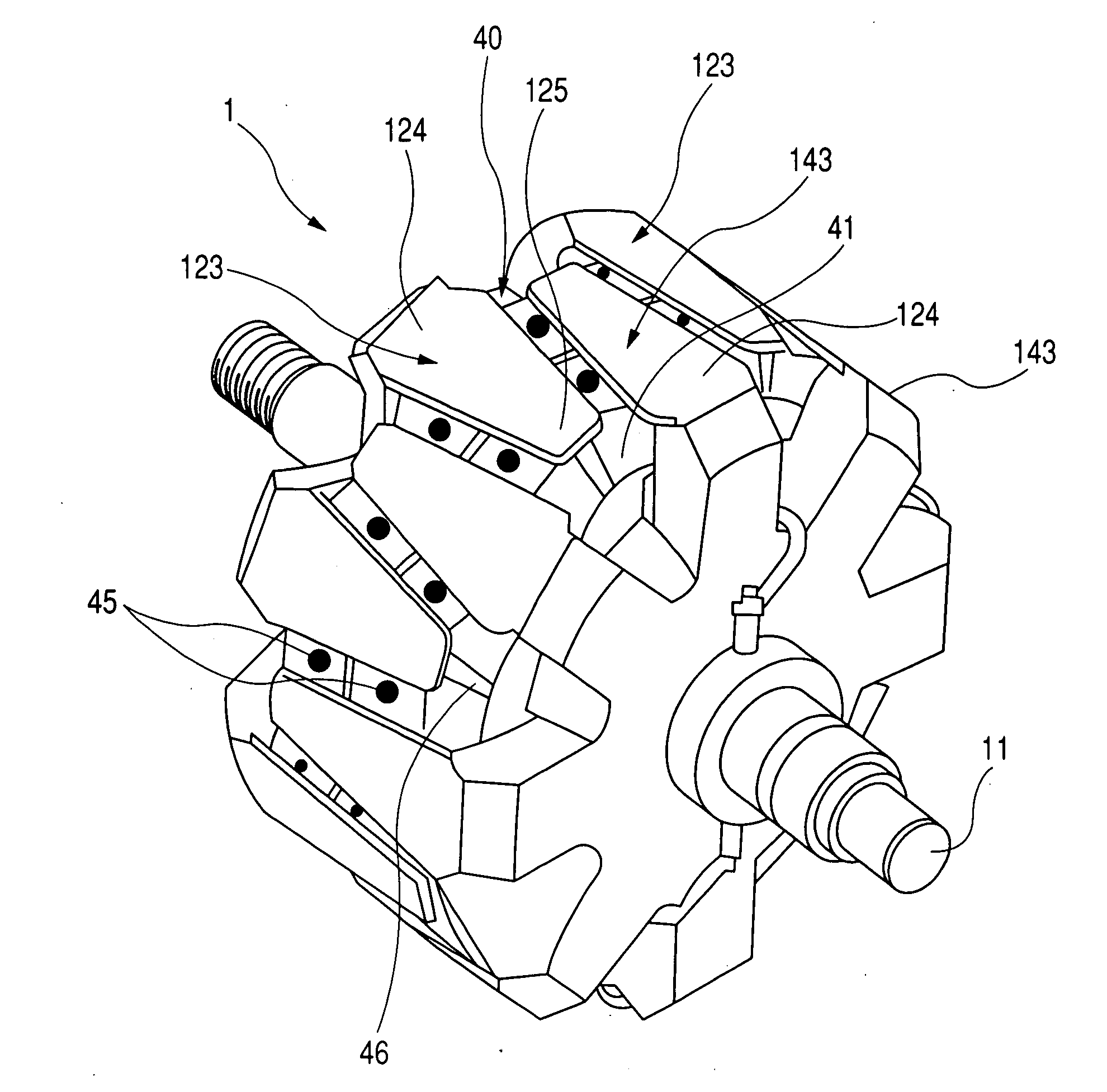
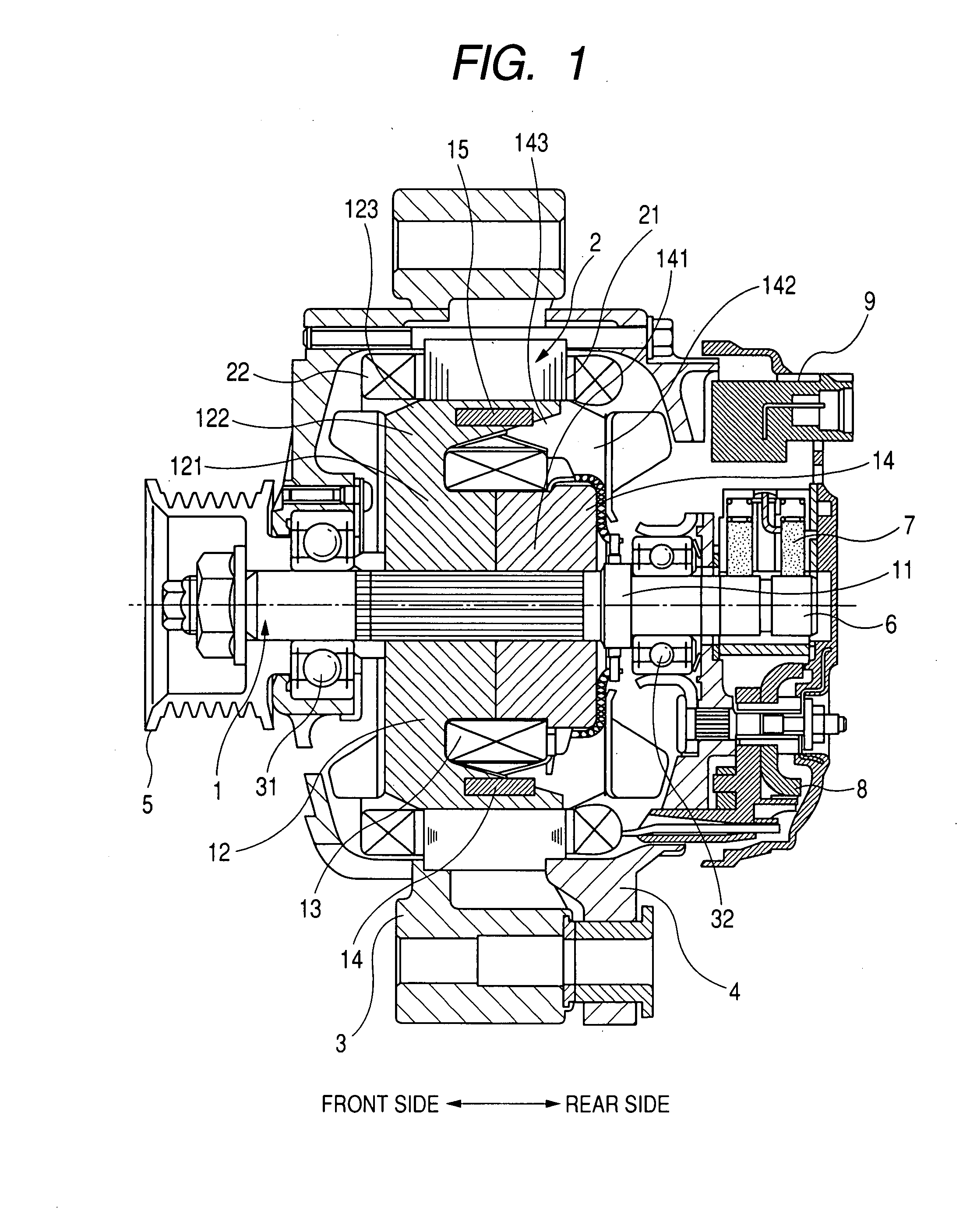
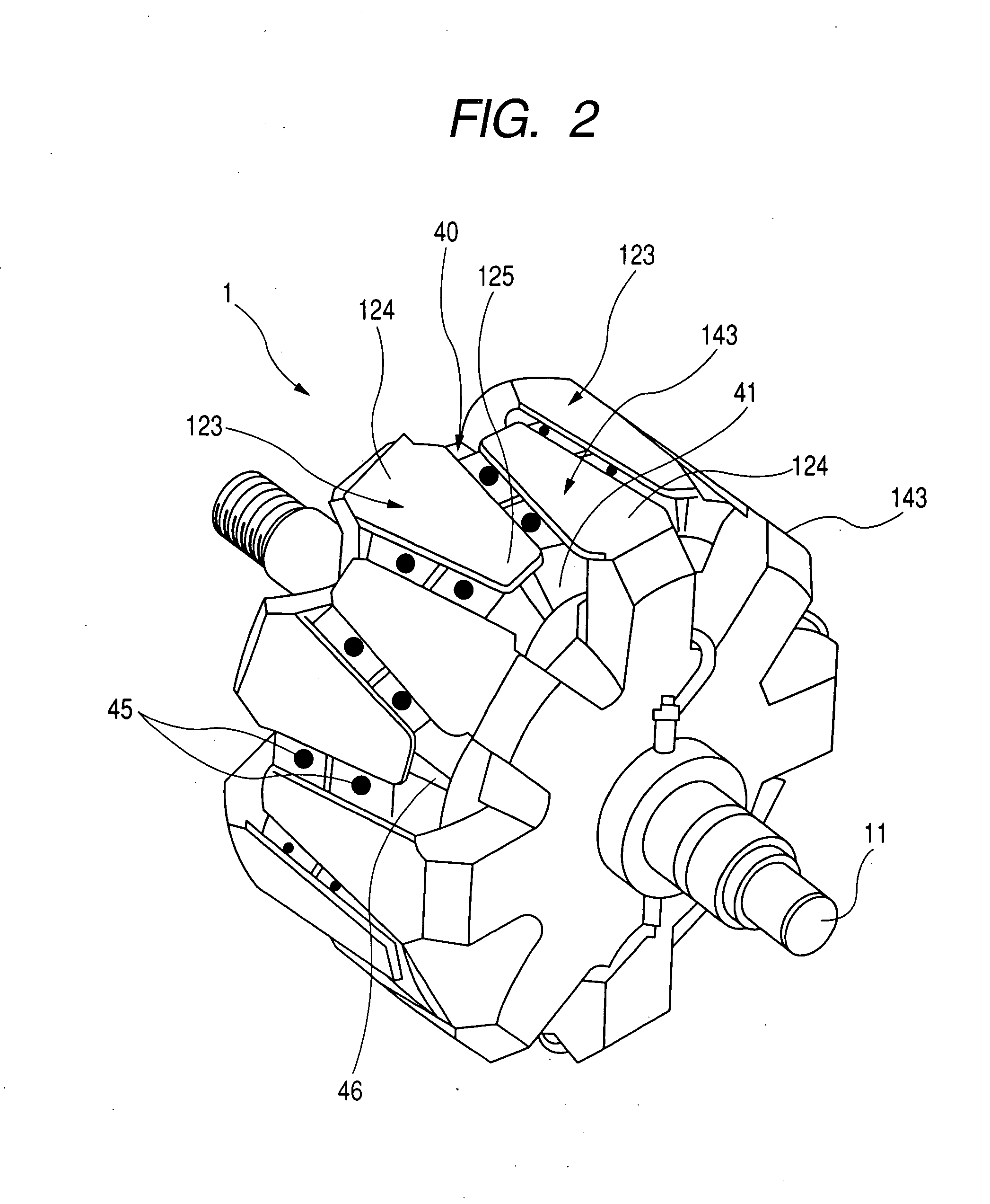
[0029]FIG. 1 is a sectional view of the vehicular alternator in an axial direction thereof according to an embodiment of the present invention. The vehicular alternator shown in FIG. 1 is equipped with a Lundell type rotor 1. As shown in FIG. 1, the vehicular alternator is mainly composed of the Lundell type rotor 1 (or the rotor 1 in short), a stator 2, a front frame 3, a rear frame 4, a pulley 5, a slip ring 6, a brush assembly 7, a rectifier 8, and a regulator 9.

[0030]The stator 2 has a stator coil 22 wound on a stator core 21 and fixed to the inner circumference surfaces of the front frame3 and the rear frame 4. The front frame 3 and the rear frame 4 accommodate the stator 2 and are fastened to each other by bolts. Further, the front frame 3 and the rear frame 4 rotatably support a rotary shaft 11 of the rotor 1 through both bearings ...


PUM

PropertyMeasurementUnit
Radiusaaaaaaaaaa
Elasticityaaaaaaaaaa

Abstract

In a vehicular alternator having a permanent magnet protection mechanism, each magnet holder of a non-magnetic characteristic if a rectangle prism shape accommodates each permanent magnet disposed between adjacent claw poles. The magnet holders are connected in a ring shape along a circumferential direction of the alternator by using each connecting plate part which extends from each magnet holder in approximate circumferential direction toward an inner side of and at a front tip part of each claw pole. The connecting plate parts and the magnet holders are made from a non-magnetic plate by cutting and bending. Making the surfaces and the connecting plate part of each magnet holder from the non-magnetic plate by cutting and bending provides a high accuracy magnet position in the alternator with low manufacturing cost.

Description

CROSS-REFERENCE TO RELATED APPLICATIONS[0001]This application is related to and claims priority from Japanese Patent Application No. 2006-226614 filed on Aug. 23, 2006, the contents of which are hereby incorporated by reference.BACKGROUND OF THE INVENTION[0002]1. Field of the invention[0003]The present invention relates to a vehicular alternator and a method of producing the vehicular alternator, in particular, relates to a vehicular alternator having a magnet protection mechanism capable of protecting permanent magnets disposed between claw poles, and a method of producing the vehicular alternator[0004]2. Description of the Related Art[0005]As rotor of a vehicular alternator, there is a Lundell type rotor mechanism composed of odd-number claw poles and even number claw poles. Each of odd number claw poles is supported at one end part in an axial direction of the rotor and extending toward the axial direction. Each of an even number of claw poles is supported at another part and ext...

Claims


Application Information

Patent Timeline
IPC IPC(8): H02K1/27H02K1/28H02K15/03
CPCY10T29/49012H02K21/044
Inventor OOWATARI, SHINYATAN, YOSHIKIMATSUBARA, SHINICHIKOUMURA, MASATOSHI
Owner DENSO CORP
Why Eureka
Try Eureka