Electrical machine and use thereof

a technology of electric machines and electric motors, applied in the field of electric machines, can solve the problems of low power factor of high torque density of known transversal-flux machines, weak magnetic coupling between stators and moving elements or rotors, and part of magnetic flux disappearing from imaginary magnetic flux circuits without performing any work, etc., to achieve small magnetic leakage, improve power factor, and high torque density

Inactive Publication Date: 2006-06-22
VOLVO TECH
View PDF24 Cites 24 Cited by
  • Summary
  • Abstract
  • Description
  • Claims
  • Application Information

AI Technical Summary

Benefits of technology

[0006] The object of the present invention is to provide an electrical machine of the transversal-flux type with a high torque density and with improved power factor, that is, with a small magnetic leakage.
[0008] With such a secondary magnet, the magnetic flux leakage in the movable element between adjacent permanent magnets may be reduced by compensating the secondary magnet for the leakage. The secondary magnet creates an addition of magnetic flux from the rotor to the stator in a magnetic flux circuit and from the stator to the rotor in an adjacent magnetic flux circuit. More exactly, the magnetic direction of the secondary magnet may advantageously extend essentially parallel to the movement path. The movement path may be a straight or somewhat curved line, along which the movable element moves, for example in a reciprocating motion. The movement path may also consist of a circle, whereby the movable element rotates around a centre point.
[0010] According to a further embodiment of the invention, each intermediate member of the movable element comprises a layer of a magnetically insulating material outside of the two secondary magnets. Such a layer may, for example, be formed from non-magnetic material, such as stainless steel, and contributes to prevent demagnetization of the secondary magnets by so-called armature reaction.
[0011] According to still another embodiment of the invention, each permanent-magnet member comprises a first magnetic flux conductor on one side of the primary magnet and a second magnetic flux conductor on the other side of the primary magnet. Further, the secondary magnets of an intermediate member between two adjacent permanent-magnet members may advantageously be arranged in such a way that the first secondary magnet extends between said first magnetic flux conductor of the two permanent-magnet members and so that the second secondary magnet extends between said second magnetic flux conductor of the two permanent-magnet members. With such a design, the north poles of two secondary magnets and one primary magnet may all be directed towards, for example, the first magnetic flux conductor and the south poles of two secondary magnets and one primary magnet all be directed towards, for example, the second magnetic flux conductor. In this way, the total pole area towards the magnetic flux conductors will be large and the magnetic flux conductors will concentrate the magnetic flux in a direction to or from the stator.
[0013] According to a still further embodiment of the invention, the essentially closed winding path comprises a second current-carrying section extending essentially parallel to the movement path. In this way, a very large part of the essentially closed winding path may be utilized for generation of current and hence the losses are kept at a very low level. Further, the first current-carrying section of the winding path may be associated with essentially a first half of said magnetic flux conductors and the second current-carrying section of the winding path be associated with an essentially second half of said magnetic flux conductors. Preferably, the permanent-magnet members of the movable element are adapted to cooperate with those magnetic flux conductors of the stator which are associated with the first current-carrying section, and those magnetic flux conductors of the stator which are associated with the second current-carrying section.
[0014] According to an additional embodiment of the invention, each magnetic flux conductor comprises at least one magnetic flux-conducting section, wherein said sections of each magnetic flux conductor are arranged in a line one after the other which is parallel to the movement path, wherein the magnetic flux of said sections of each magnetic flux conductor extends essentially in the same direction and wherein a dividing member is arranged between each pair of adjacent magnetic flux conductors and comprises main sections that include a magnetically conducting material and extend along said sections. In such a magnetic flux-conducting dividing member and adjacent sections of the magnetic flux conductors, the magnetic flux will extend in the same direction, which means that the magnetic leakage between the magnetic flux conductors may be reduced considerably. So-called flux fringing in the stator may thus be essentially prevented. Said sections advantageously form a magnetic flux-conducting central section. Further, each magnetic flux conductor may comprise at least said central section and two magnetic flux-conducting end sections adjoining an air gap between the stator and the movable element. Each dividing member is preferably magnetically insulating along the end sections, which prevent magnetic leakage caused by the opposite magnetic flux direction of adjacent permanent-magnet members of the movable element. The magnetic insulation may advantageously be achieved in such a way that each dividing member forms a space with air along the end sections. The main section of said dividing member may be made of magnetically conducting iron.

Problems solved by technology

However, the high torque density of known transversal-flux machines is associated with a relatively low power factor, that is, both the machine and the control unit must be designed for relatively great dimensional outputs compared with their active rated powers.
The reason for the low power factor is that known transversal-flux machines have a relatively great leakage of the magnetic flux, which results in a weak magnetic coupling between the stator and the movable element or rotor.
The magnetic leakage, which is of a certain magnitude in all types of electrical machines, means that part of the magnetic flux disappears from the imaginary magnetic flux circuit without performing any work.
The leakage thus deteriorates the efficiency of the machine.

Method used


Image

  • Electrical machine and use thereof
  • Electrical machine and use thereof
  • Electrical machine and use thereof

Examples


first embodiment

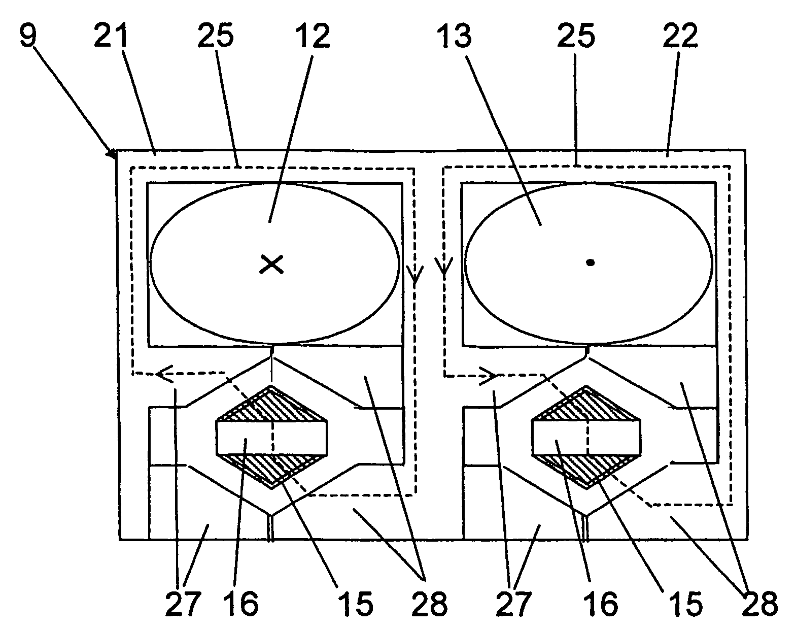
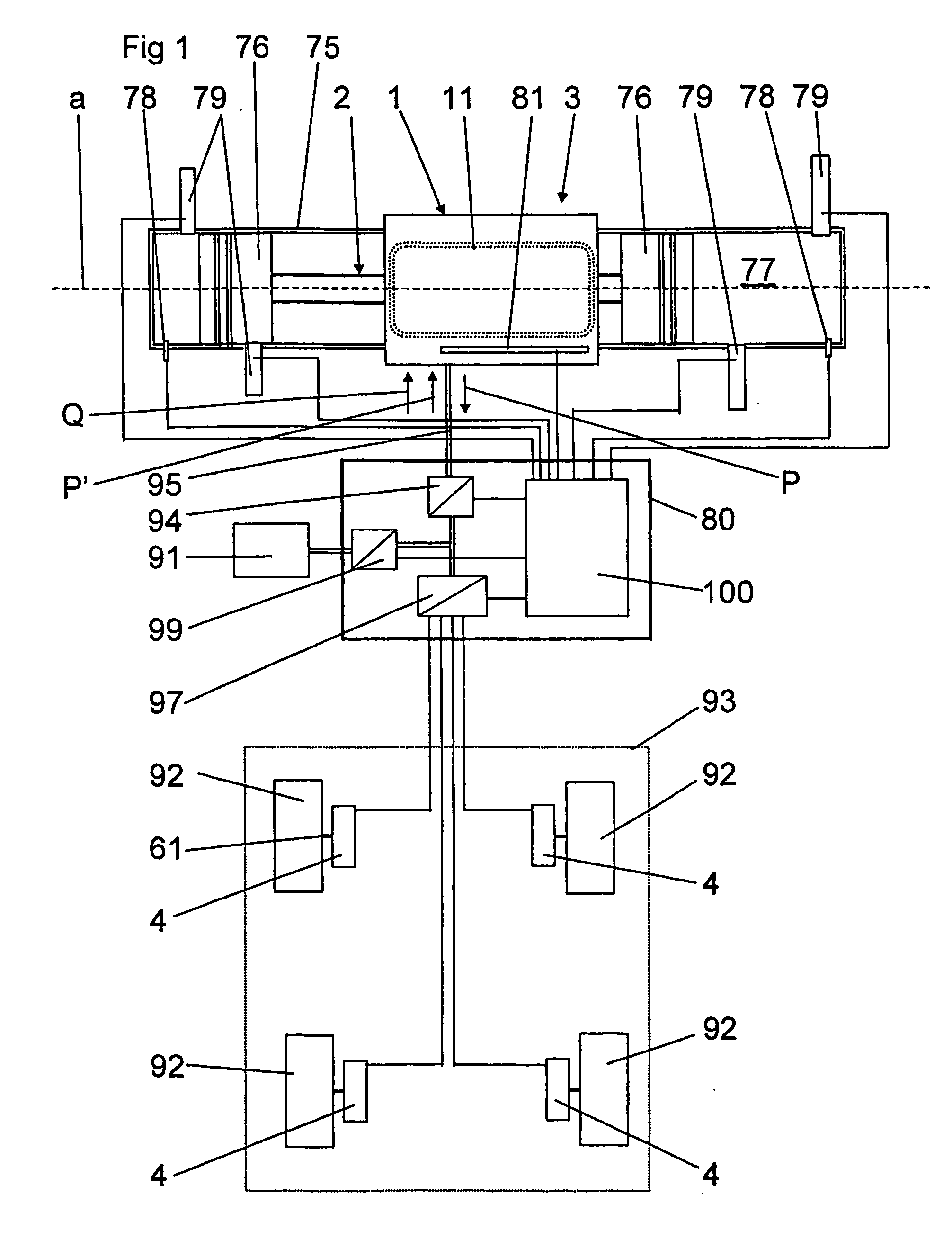
[0033] The present invention relates to an electrical machine of the transversal-flux type. The electrical machine comprises a stator 1 and a movable element 2. FIG. 1 schematically shows a linear electrical machine 3 according to the invention with a movable element 2 moving in relation to the stator 1 back and forth along an essentially rectilinear movement path extending parallel to the axis a. It should be noted that in this application, the expression linear electrical machine also relates to the case where the movable element 2 moves back and forth along an arched movement path.

second embodiment

[0034]FIG. 8 schematically shows a rotating electrical machine 4 according to the invention with a movable element 2 in the form of a rotor rotating around a centre axis b, the movement path extending along a circle around the centre axis b. In this case, as in the arched case above, the term movement path, in the expressions “across the movement path” and “parallel to the movement path”, respectively, means the tangent to the movement path in the position in question.

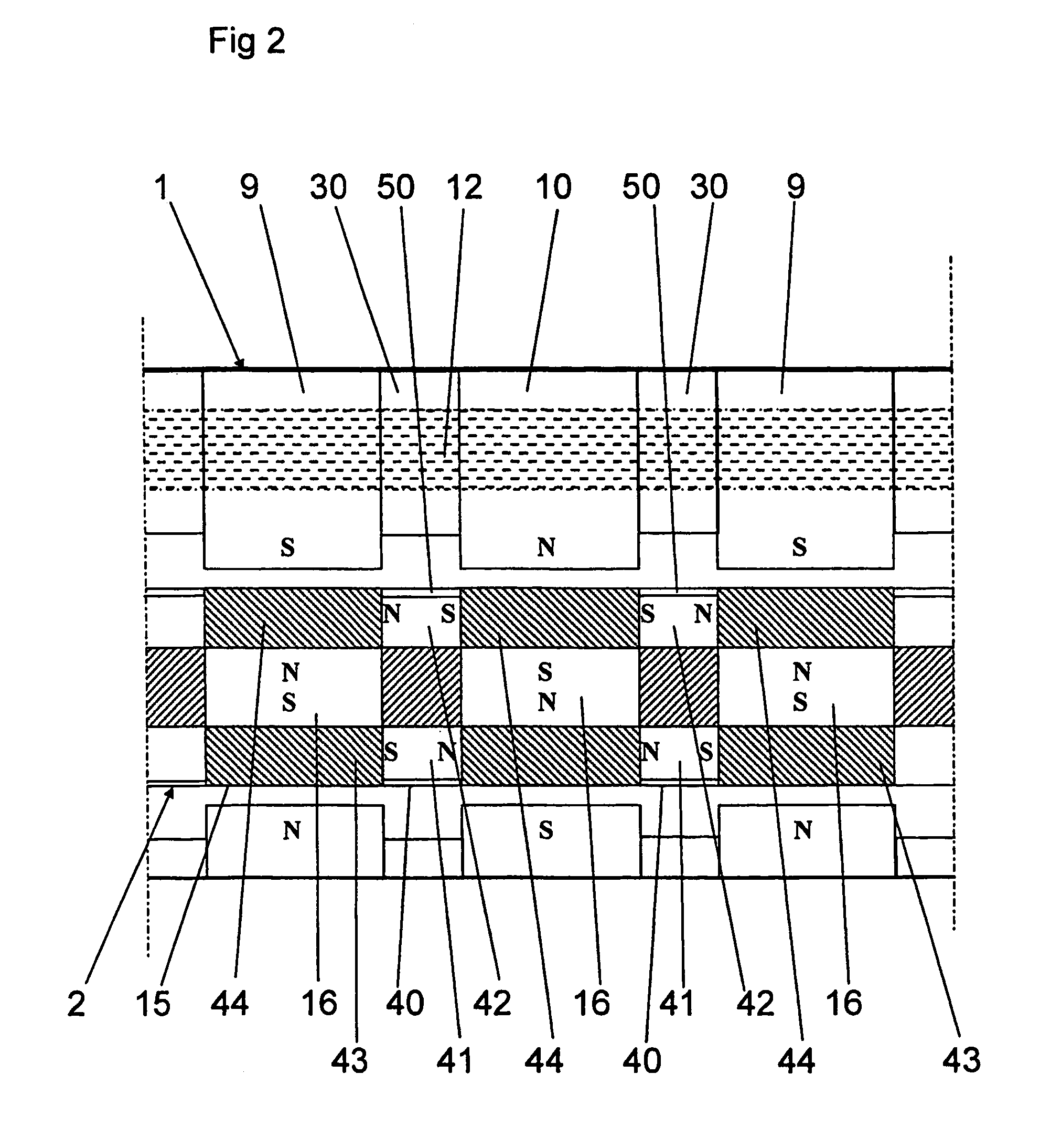
[0035] In the following, the first embodiment will first be described with reference to FIGS. 1-7, wherein FIG. 2 only shows a schematic composition whereas FIGS. 3-7 show more of a possible design. The stator 1 comprises a plurality of stator elements 9, 10 (see FIG. 2) and an electric conductor that forms a winding 11 extending in an essentially closed winding path, which is schematically indicated in FIG. 1. The winding 11 extends through each stator element 9, 10. In the embodiment shown in FIGS. 2-7, the essential...


PUM


Abstract

The invention relates to an electrical machine of the transversal-flux type. The machine comprises a stator and a movable element. The stator has a plurality of stator elements with magnetic flux conductors and an electric winding extending in a closed winding path through each magnetic flux conductor. The movable element comprises a number of permanent-magnet members and is movable in relation to the stator along a movement path. The winding path comprises a first current-carrying section extending along the movement path. Each magnetic flux conductor forms, together with one of the permanent-magnet members, a closed magnetic flux circuit around said current-carrying section. Each permanent-magnet member comprises a primary magnet with a magnetic direction across the movement path. Adjacently located permanent-magnet members are separated from each other by an intermediate member comprising at least one secondary magnet that has a magnetic direction essentially across the magnetic direction of the primary magnet.

Description

TECHNICAL FIELD AND BACKGROUND ART [0001] The present invention relates to an electrical machine of the transversal-flux type according to the preamble to claim 1 (see WO01 / 78218 (ABB AB) and WO01 / 78219 (ABB AB)). The invention also relates to a use of such an electrical machine. [0002] Conventional electrical machines operate according to the so-called longitudinal-flux principle, which means that the magnetic flux plane of each stator element is parallel to the direction of movement of the rotor. U.S. Pat. No. 5,177,142 (Von Zweygbergk) discloses an electrical machine that operates according to the so-called transversal-flux principle. This known machine comprises a rotating rotor with a number of permanent magnets and a stator with a corresponding number of stator elements that are arranged in such a way that the induced magnetic flux substantially follows a path perpendicular to the direction of rotation of the rotor. The known machine is characterized by a high power or torque ...

Claims


Application Information

Patent Timeline
Patent Type & Authority Applications(United States)
IPC IPC(8): H02K21/12F02B1/12H02K7/18H02K35/02H02K41/03
CPCF02B1/12H02K7/1823H02K7/183H02K7/1876H02K21/125H02K35/02H02K41/031H02K2201/12
Inventor SADARANGANI, CHANDURBACKSTROM, THOMASARSHAD, WAQAS M.
Owner VOLVO TECH
Why Eureka
Try Eureka