Direct drive type sinusoidal magnetic field composite permanent magnet motor

A permanent magnet motor, composite technology, applied in the direction of electrical components, electromechanical devices, magnetic circuit static parts, etc.

Active Publication Date: 2011-04-27
SHANGHAI UNIV
View PDF3 Cites 23 Cited by
  • Summary
  • Abstract
  • Description
  • Claims
  • Application Information

AI Technical Summary

Problems solved by technology

[0003] The purpose of the present invention is to solve the problem that the harmonic magnetic field of the magnetic gear in the radially magnetized permanent magnet composite motor affects the smooth and efficient operation of the embedded permanent magnet motor, and provides a Direct drive sinusoidal magnetic field composite permanent magnet motor, compact structure, high torque density, suitable for low speed, high torque direct drive occasions

Method used


Image

  • Direct drive type sinusoidal magnetic field composite permanent magnet motor
  • Direct drive type sinusoidal magnetic field composite permanent magnet motor
  • Direct drive type sinusoidal magnetic field composite permanent magnet motor

Examples


Embodiment 1

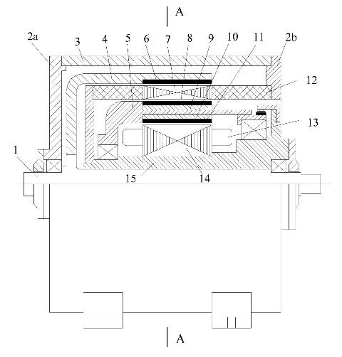
[0021] Embodiment one: see figure 1 , the direct-drive sinusoidal magnetic field composite permanent magnet motor includes a self-controlled permanent magnet motor and a magnetic field modulation magnetic gear, which is characterized in that the permanent magnet motor and the magnetic gear both adopt a sinusoidal magnetized permanent magnet structure; and both Those are concentrically assembled into a double-stator double-rotor structure, that is, the outer rotor 4 and outer stator 7 that constitute the magnetic gear and the inner rotor 5 and inner stator 15 that constitute the permanent magnet motor adopt a sleeve-type structure to form a concentric structure.

Embodiment 2

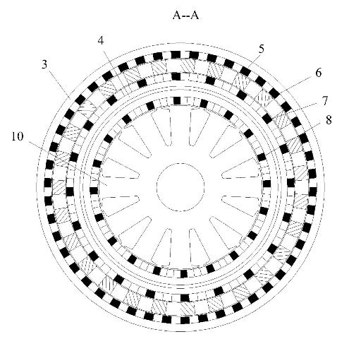
[0022] Embodiment two: see figure 1 , figure 2 , image 3 , this embodiment is basically the same as Embodiment 1, and the special features are as follows: the outer rotor 4 is a cup-shaped rotor, and its cup-shaped bottom is fixedly connected with an outer rotor central shaft 1; the outer stator 7 is a cylindrical body, which is composed of Iron core blocks and non-magnetic materials are alternately spaced circumferentially, one end of which is directly connected to an end cover 2b of a frame 3 through an axial support 12, and the other end is connected to the inner stator 15 through a radial disc The inner end of the inner rotor is fixedly connected; the inner rotor 5 is a cylindrical body, which consists of an outer permanent magnet 8, an outer iron yoke 9, a stainless steel magnetic isolation cylinder, an inner iron yoke 10 and an inner layer The permanent magnet 11 is set, and the two ends of the stainless steel magnetic isolation cylinder are supported by two bearing...

Embodiment 3

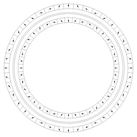
[0030] Embodiment 3: This embodiment is basically the same as Embodiment 2. Its structure and working principle are as follows: the main shaft 1 of the sinusoidal magnetic field composite permanent magnet motor is connected with the outer rotor 4, and the output is low-speed and high-torque. The outer rotor permanent magnet 6, the inner rotor The outer permanent magnet 8 of the rotor 5 and the inner permanent magnet 11 are all sinusoidal magnetization (Halbach) structures, and the number of pole pairs of the inner rotor is P 2 , the number of outer rotor pole pairs P 1 , and P 1 >P 2. Therefore, the rotation speed of the outer rotor 4 is low, and the rotation speed of the inner rotor 5 is high. Between the outer rotor 4 and the inner rotor 5 is a reluctance type outer stator 7, and the reluctance type stator has N s A uniformly distributed iron core tooth pole, the slot is filled with non-magnetic material to enhance the mechanical strength. The outer permanent magnet 8 o...


PUM


Abstract

The invention relates to a direct drive type sinusoidal magnetic field composite permanent magnet motor which comprises a self-control type permanent magnet motor and a magnetic field modulating type magnetic gear, wherein both the permanent magnet motor and the magnetic gear adopt a sinusoidal magnetizing permanent magnet structure and are concentrically integrated into a double-stator double-rotor structure, i.e. an outer rotor and an outer stator constituting the magnetic gear and an inner rotor and an inner stator constituting the permanent magnet motor are integrated into a concentric type structure by adopting a sleeve type structure. The invention has the advantages of compact structure, high torque density, high efficiency, high power factor, inherent overloading protection characteristic, and the like.

Description

technical field [0001] The invention belongs to the field of motor and transmission technology, and specifically relates to a low-speed, high-torque direct-drive sinusoidal magnetic field composite permanent magnet motor. The motor is a combination of a sinusoidal magnetic field concentric magnetic gear and a sinusoidal magnetic field self-controlled permanent magnet motor. Integrated to form a permanent magnet motor with high torque density, high efficiency and high power factor. Background technique [0002] A traditional motor drive system is a combination of an electric motor and a mechanical transmission mechanism. However, the daily maintenance of mechanical transmission components (such as gear boxes) and the replacement of wearing parts need to pay extra costs, and the cost of regular maintenance for long-distance running systems will be extremely expensive; the clearance between mechanical transmission components and The loss makes it difficult to realize high-prec...

Claims


Application Information

Patent Timeline
Patent Type & Authority Applications(China)
IPC IPC(8): H02K16/00H02K1/27H02K1/14H02K1/16
Inventor 章跃进江建中杜世勤龚宇崔巍仇志坚
Owner SHANGHAI UNIV
Why Eureka
Try Eureka