
Stator permanent-magnetic doubly salient disc-type motor

A disc motor and double salient pole technology, applied in the direction of motor, magnetic circuit shape/style/structure, electric vehicles, etc., can solve the problems of inconvenient use, long axial length, etc., to prevent damage, facilitate installation, and reduce consumption Effect

Active Publication Date: 2016-01-13
NANJING UNIV OF SCI & TECH
View PDF4 Cites 24 Cited by
  • Summary
  • Abstract
  • Description
  • Claims
  • Application Information

AI Technical Summary

Problems solved by technology

However, the current doubly salient pole motor has a long axial length, so it is inconvenient to use in places where the axial space is limited

Method used


Image

  • Stator permanent-magnetic doubly salient disc-type motor
  • Stator permanent-magnetic doubly salient disc-type motor
  • Stator permanent-magnetic doubly salient disc-type motor

Examples


Embodiment 1

[0024] Taking the three-phase stator permanent magnet double salient pole disc motor as an example

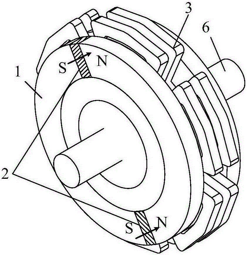
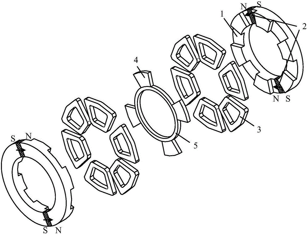
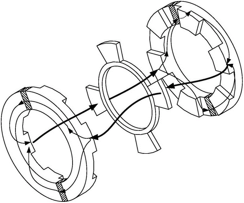
[0025] to combine figure 1 , figure 2 and image 3 , the stator permanent magnet double salient pole disc motor includes a rotor mechanism, a motor shaft 6 and two identical stator mechanisms, the rotor mechanism is placed between the two stator mechanisms, the stator mechanism is connected to the motor shaft 6 through a bearing, and the rotor mechanism is fixed Connected to the motor shaft 6, the stator mechanism includes a stator core 1, two permanent magnets 2 and 6 annular armature windings 3, the stator core 1 is annular, and 6 stator teeth are evenly distributed on the inner wall of the stator core 1, and the stator teeth constitute the stator Salient poles, the slots between two adjacent stator teeth are stator slots, and permanent magnets 2 are respectively arranged in the center of any pair of stator slots on the same diameter, and the permanent magnets 2 are magnet...

Embodiment 2

[0031] Taking the four-phase stator permanent magnet double salient pole disc motor as an example

[0032] to combine figure 1 , figure 2 and image 3 , a stator permanent magnet double salient pole disc motor, comprising a rotor mechanism, a motor shaft 6 and two identical stator mechanisms, the rotor mechanism is placed between the two stator mechanisms, the stator mechanism is connected to the motor shaft 6 through a bearing, The rotor mechanism is fixed on the motor shaft 6. The stator mechanism includes a stator core 1, two permanent magnets 2 and 8 annular armature windings 3. The stator core 1 is ring-shaped, and 8 stator teeth are evenly distributed on the inner wall of the stator core 1. The stator The teeth constitute the salient poles of the stator, and the slots in the middle of two adjacent stator teeth are stator slots. A permanent magnet 2 is respectively arranged in the center of any pair of stator slots located on the same diameter, and the permanent magnet...


PUM


Abstract

The present invention discloses a stator permanent-magnetic doubly salient disc-type motor, which comprises stator mechanisms, a rotor mechanism and a motor shaft, wherein the rotor mechanism is arranged between the two stator mechanisms, the rotor mechanism and the stator mechanisms are arranged on the motor shaft, each stator mechanism comprises a stator core, two permanent magnets and 2N annular armature windings, 2N stator teeth are evenly distributed on the inner wall of each stator core, a groove between every two adjacent stator teeth is a stator groove, the permanent magnets magnetized in the peripheral direction are arranged in centers of any pair of stator grooves on the same diameter, and the 2N annular armature windings respectively sleeve the 2N stator teeth; and the rotor mechanism comprises a plurality of rotor cores and a non-magnetic-conductive rotor bracket, the plurality of rotor cores are evenly distributed on the outer circumference of the non-magnetic-conductive rotor bracket, and the rotor cores form rotor salient poles. The stator permanent-magnetic doubly salient disc-type motor can effectively improve the reliability of the motor, reduces size and weight of the motor, improves power density and torque density of the motor, and is suitable to be used in occasions with strict requirements on size of generators or motors.

Description

technical field [0001] The invention belongs to the field of motors, in particular to a stator permanent magnet double salient pole disc motor. Background technique [0002] With the development of the new energy industry, wind power, electric vehicles and other fields have become an important part of my country's energy development strategy. Motors are the main equipment for energy conversion. Motors for wind power generation and electric vehicles have become the main research hotspots at this stage. The quality of their electrical and mechanical properties directly affects the efficiency of energy conversion and the cost and reliability of control systems. [0003] Because the disc motor belongs to the axial field motor, it has the characteristics of short axial dimension, compact structure, light weight, small volume, high power density, etc., so it is especially suitable for occasions with special requirements for motor volume such as wind power generation and electric v...

Claims


Application Information

Patent Timeline
Patent Type & Authority Applications(China)
IPC IPC(8): H02K16/04H02K1/17H02K1/14H02K1/24
CPCY02T10/64
Inventor 颜建虎杨凯张尚坤
Owner NANJING UNIV OF SCI & TECH
Learn More