Heat-treating furnace with magnetic field and heat treatment method using same

a heat treatment method and furnace technology, applied in the direction of furnaces, heat treatment equipment, lighting and heating equipment, etc., can solve the problems of large electricity cost for generating a magnetic field, high treatment cost, and unsatisfactory safety aspects, and achieve the effect of reducing the leakage of magnetic fields

Inactive Publication Date: 2004-12-21
HITACHI METALS LTD
View PDF4 Cites 19 Cited by
  • Summary
  • Abstract
  • Description
  • Claims
  • Application Information

AI Technical Summary

Benefits of technology

Accordingly, an object of the present invention is to provide a small, high-safety, high-accuracy, heat-treating furnace with a uniform parallel magnetic field and reduced magnetic field leakage.
As shown in FIG. 1(a), the first heat-treating furnace with a magnetic field of the present invention comprises a heat treatment means comprising a heat-treating container 6 and a heating means 5, and a ring-shaped, permanent magnet assembly 1 disposed around the heat treatment means via a cooling means 3, whereby a uniform magnetic field can stably be generated in one direction in a horizontal plane at a low cost.
Also, as shown in FIG. 1(b), the second heat-treating furnace with a magnetic field of the present invention comprises a heat treatment means comprising a heat-treating container 6 and a heating means 5, and a magnetic field-generating means disposed around the heat treatment means via a cooling means 3, the magnetic field-generating means being a double ring-type, Halbach-type magnetic circuit constituted by an inner, ring-shaped, permanent magnet assembly 1 and an outer, ring-shaped, permanent magnet assembly 2, whereby a uniform magnetic field can stably be generated in one direction in a horizontal plane and in a relatively limited range in an axial direction at a low cost. The magnetic field strength in the center hole 20 can be controlled arbitrarily. Accordingly, it is suitable for heat-treating a plurality of relatively thin, large-diameter (for instance, 6-8 inches or more) wafer substrates A with thin magnetic layers at a time.
To reduce a leaked magnetic flux, the outer, ring-shaped, permanent magnet assembly 2 is desirably shorter in an axial direction than the inner, ring-shaped, permanent magnet assembly 1. With the inner, ring-shaped, permanent magnet assembly 1 and / or the outer, ring-shaped, permanent magnet assembly 2 becoming shorter toward outside in a radial direction, the leaked magnetic field is further reduced in an axial direction. With such a structure, the leaked magnetic flux of the ring-shaped magnetic circuit can be made small, enabling the reduction in size and weight of the magnetic circuit.
In the heat-treating furnace with a magnetic field of the present invention, as shown in FIG. 1, the heat treatment means comprises a cooling means 3 having a case with a mirror surface and a cooling pipe 4 contained in the case, a heating means 5 such as a carbon heater embedded in a quartz glass, and a vacuum container 6 made of a transparent quartz glass, into which a heat-treating holder 10 holding a plurality of articles A to be heat-treated is introduced. With this heat treatment means, a magnetic field center of the magnetic field-generating means consisting of the inner, ring-shaped, permanent magnet assembly 1 and the outer, ring-shaped, permanent magnet assembly 2 is easily aligned with a center of an assembly of articles A to be heat-treated. Because there is a cooling means 3 between the heating means 5 and the magnetic field-generating means, the permanent magnets are protected from thermal influence. Accordingly, despite the heat treatment temperature at about 250-300.degree. C., the permanent magnets are not thermally deteriorated. Incidentally, the heat treatment means may be placed in a non-oxidizing atmosphere such as a nitrogen gas.

Problems solved by technology

However, the magnetic field-generating means in this heat-treating furnace with a magnetic field is constituted by an electromagnet having a coil, to which as large electric current as 500-800 A should be supplied to generate a magnetic field of 1.0 T or more, unsatisfactory from the aspect of safety.
It also needs a facility for using large electric power, taking large electricity cost for generating a magnetic field, and a large amount of cooling water should be used to remove heat generated by large electric current.
Because of these requirements, it suffers from high treatment cost.
Though the consumption of exciting current can be made smaller when a superconductive coil is used than when the electromagnet is used, liquid nitrogen or helium should always be consumed to keep superconductivity, resulting in high operation cost.
Also, in a system using a superconductive coil, the variation of a magnetic field turns superconductivity to normal conductivity locally, resulting in heat generation in the coil, and if this state were left to stand, the superconductivity of the entire apparatus would be destroyed.
Accordingly, it suffers from the problem of a leaked magnetic field like the electromagnet.
However, a conventional heat-treating furnace comprising an electromagnet fails to generate a uniform magnetic field in parallel with the thin magnetic layers.

Method used


Image

  • Heat-treating furnace with magnetic field and heat treatment method using same
  • Heat-treating furnace with magnetic field and heat treatment method using same
  • Heat-treating furnace with magnetic field and heat treatment method using same

Examples


example 2

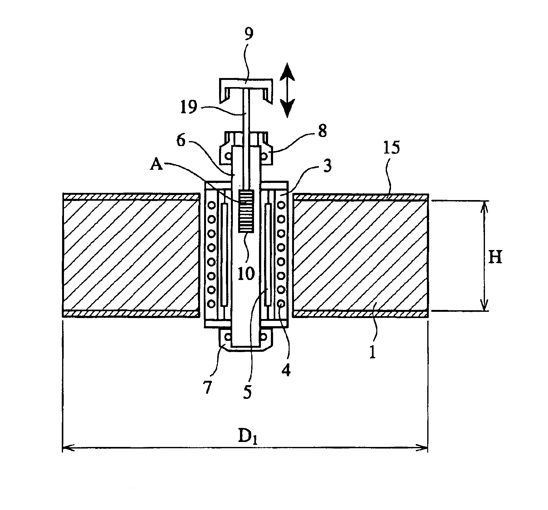
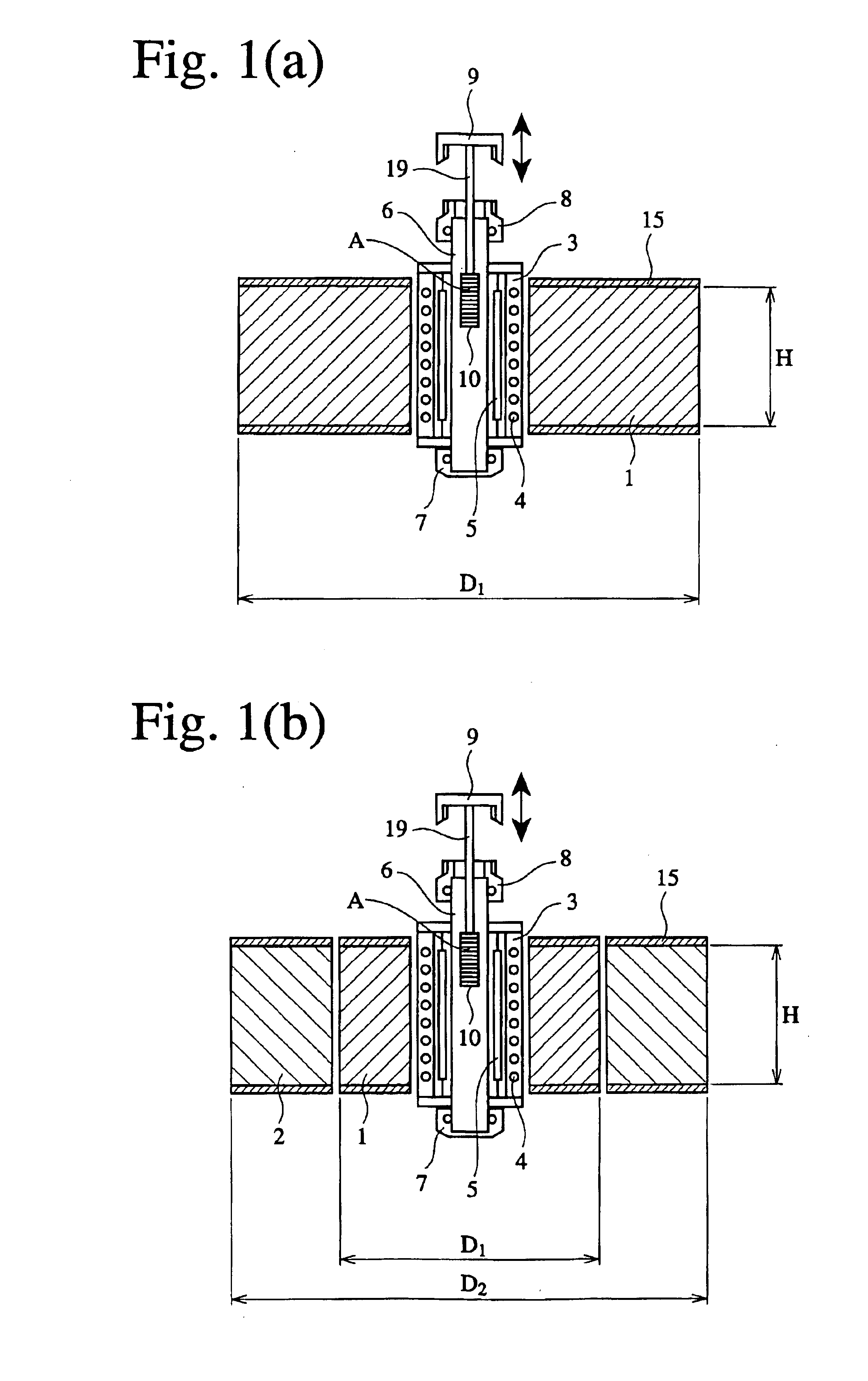
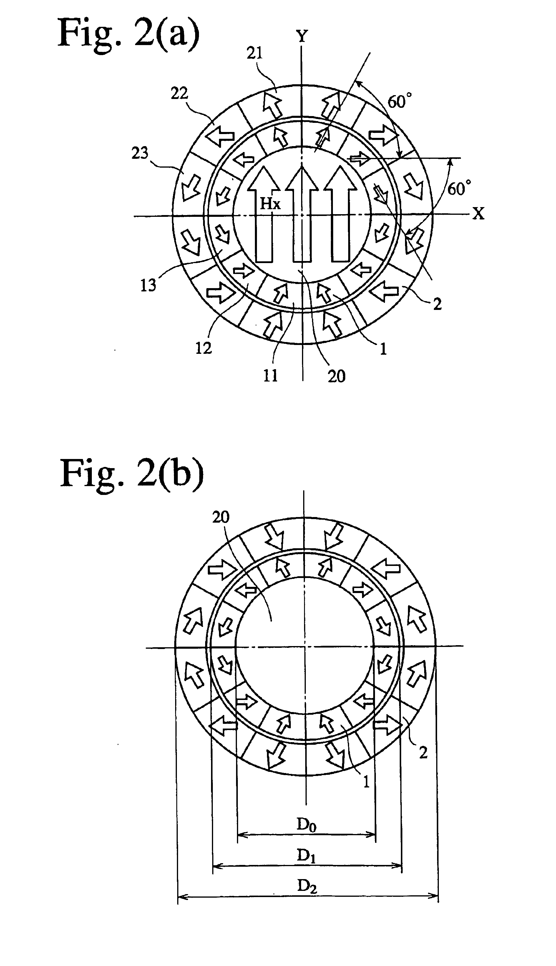
Heat treatment was carried out in a magnetic field in the same manner as in Example 1 except for changing the axial lengths of an outer, ring-shaped, permanent magnet assembly 2 and an inner, ring-shaped, permanent magnet assembly 1A as shown in FIG. 3, and preventing the wafer substrates from rotating with the inner, ring-shaped, permanent magnet assembly 1A. Each ring-shaped, permanent magnet assembly was constituted by three types of fan-shaped permanent magnet segments having different magnetization directions, which were arranged in the number of 12 in a peripheral direction. Each permanent magnet segment has the same magnetization direction as shown in FIG. 2.

As a heat-treating furnace with a magnetic field for 8-inch wafer substrates, the inner, ring-shaped, permanent magnet assembly 1A had an inner diameter D.sub.0 of 360 mm and an outer diameter D.sub.1 of 560 mm. The outer, ring-shaped, permanent magnet assembly 2A had an outer diameter D.sub.2 of 1100 mm. The inner, ring-...

example 3

A heat-treating furnace with a magnetic field comprising an inner, ring-shaped, permanent magnet assembly 1 and an outer, ring-shaped, permanent magnet assembly 2 each constituted by 12 permanent magnet segments having magnetization directions shown in FIG. 2 was used as in Example 1. The inner, ring-shaped, permanent magnet assembly 1 had an inner diameter D.sub.0 of 360 mm and an outer diameter D.sub.1 of 560 mm. The outer, ring-shaped, permanent magnet assembly 2 had an outer diameter D.sub.2 of 1100 mm. Both ring-shaped, permanent magnet assemblies 1, 2 had an axial length (height) H of 420 mm.

The inner, ring-shaped, permanent magnet assembly 1 has a case 11 provided with a gear on a lower surface, so that it is rotatable relative to the outer, ring-shaped, permanent magnet assembly 2 and the wafer substrates by a motor. Accordingly, the relative position of the wafer substrates to the inner, ring-shaped, permanent magnet assembly 1 changed. This Example is the same as Example 1...

example 4

FIG. 4 shows another example of a combination of an inner, ring-shaped, permanent magnet assembly 1B and an outer, ring-shaped, permanent magnet assembly 2B. The outer, ring-shaped, permanent magnet assembly 2B is shorter in an axial length (height) than the inner, ring-shaped, permanent magnet assembly 1B. In the embodiment of FIG. 5, the outer, ring-shaped, permanent magnet assembly 2C is shorter in an axial length (height) than the inner, ring-shaped, permanent magnet assembly 1C, and the inner and outer ring-shaped, permanent magnet assemblies 1C, 2C have an axial length, which becomes gradually shorter as it goes toward outside in a radial direction. With this structure, the leaked magnetic field in an axial direction can be reduced. This can make the ring-shaped, permanent magnet assemblies smaller and lighter in weight, resulting in a shorter heat-treating furnace with a magnetic field.

FIG. 6(a) shows an installation example, in which an outer, ring-shaped, permanent magnet a...


PUM

PropertyMeasurementUnit
axial lengthaaaaaaaaaa
outer diameteraaaaaaaaaa

Abstract

A heat-treating furnace with a magnetic field comprising (a) a magnetic field-generating means constituted by an outer, ring-shaped, permanent magnet assembly comprising a plurality of permanent magnet segments combined with their magnetization directions oriented such that a magnetic flux flows in a diameter direction, and an inner, ring-shaped, permanent magnet assembly disposed inside the outer, ring-shaped, permanent magnet assembly and comprising a plurality of permanent magnet segments combined with their magnetization directions oriented such that a magnetic flux flows in a diameter direction; and (b) a heat treatment means disposed in a center hole of the inner, ring-shaped, permanent magnet assembly and comprising a cooling means, a heating means, and a heat-treating container containing heat-treating holder for holding a plurality of articles to be heat-treated in this order from outside, wherein an axial center of a magnetic field generated by the inner and outer ring-shaped, permanent magnet assemblies is substantially identical with an axial center of an article assembly in the heat-treating container.

Description

The present invention relates to a furnace for heat-treating wafer substrates for forming MR (magnetoresistive) heads, GMR (giant magnetoresistive) heads, MRAM (magnetic random access memory), etc. in a magnetic field in their production processes, and a heat treatment method using such a furnace.PRIOR ARTA magnetic head generally has a structure in which a plurality of ferromagnetic layers are laminated on a substrate. For instance, the GMR head has a structure comprising non-magnetic insulating layers between ferromagnetic layers. The MRAM head has a structure comprising antiferro magnetic layers, a pinned magnetic layer, a non-magnetic conductive layer and free magnetic layers in this order from the side of a substrate. The pinned magnetic layers are entirely magnetized in one direction.To magnetize the pinned layer in one direction, it is necessary to heat-treat or anneal a substrate provided with thin magnetic layers in a magnetic field. An oriented magnetic field of 0.5 T (tes...

Claims


Application Information

Patent Timeline
Patent Type & Authority Patents(United States)
IPC IPC(8): C21D1/04H05B6/22H05B6/02H01L21/68
CPCH05B6/22C21D1/04Y02P10/25H01L21/68
Inventor KURIYAMA, YOSHIHIKOUSHIJIMA, MAKOTOAZUMA, YASUYUKI
Owner HITACHI METALS LTD
Why Eureka
Try Eureka