injection molding machine

A technology of injection molding machine and supporting part, which is applied in the field of injection molding machine to achieve the effect of reducing magnetic field leakage

Inactive Publication Date: 2015-11-18
SUMITOMO HEAVY IND LTD
View PDF2 Cites 0 Cited by
  • Summary
  • Abstract
  • Description
  • Claims
  • Application Information

AI Technical Summary

Problems solved by technology

[0006] However, since the back platen described in Patent Document 1 is configured such that the back side of the back platen and the back side of the leg are continuous, the magnetic field generated by the electromagnet leaks through the leg.

Method used


Image

  • injection molding machine
  • injection molding machine
  • injection molding machine

Examples


Embodiment Construction

[0017] Hereinafter, embodiments of the present invention will be described in detail with reference to the drawings. In addition, in the present embodiment, the mold clamping device will be described assuming that the moving direction of the movable platen when the mold is closed is set to the front, and the moving direction of the movable platen when the mold is opened is set as the rear.

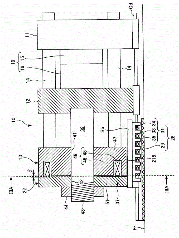
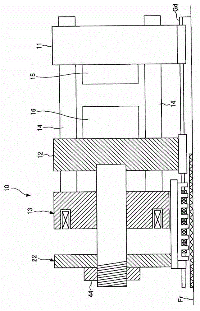
[0018] figure 1 It is a figure which shows the state at the time of mold closing of the injection molding machine concerning 1st Embodiment of this invention, figure 2 It is a figure which shows the state at the time of mold opening of the injection molding machine concerning 1st Embodiment of this invention. In addition, respectively in figure 1 and figure 2 The slanted hatching portion indicates the section of the vertical plane passing through the centerline of the injection molding machine.

[0019] figure 1 Among them, 10 represents the mold clamping device, Fr represents the f...


PUM


Abstract

The invention provides an injection moulding machine which is provided with a structure reducing magnetic field leakage of an electromagnet. The injection moulding machine is provided with a mold closing mechanism (10) which uses attraction forces of the electromagnet (49) to generate mold clamping forces. The mold closing mechanism (10) is provided with a rear platen (13) comprising an electromagnet (49), a foot portion (216) vertically supporting the rear platen (13) relative to a frame (Fr). The foot portion (216) is provided with space reducing magnetic field leakage of the electromagnet (49). The space separates at least a part between an adsorption surface (13S) of the rear platen (13) and a surface (S2) of the foot portion (216) which faces a same side with the adsorption surface (13S).

Description

technical field [0001] This application claims priority based on Japanese Patent Application No. 2011-288993 filed on December 28, 2011. The entire content of the application is incorporated in this specification by reference. [0002] The present invention relates to an injection molding machine provided with a mold clamping device that generates a mold clamping force by using an attractive force of an electromagnet. Background technique [0003] Conventionally, there is known a horizontal injection molding machine provided with a mold clamping device that generates a mold clamping force using an attractive force of an electromagnet (for example, refer to Patent Document 1). [0004] The mold clamping device of Patent Document 1 is composed of a fixed platen, a movable platen, a rear platen, a suction plate, a linear motor, an electromagnet unit, a central rod, and the like. And, the electromagnet of its electromagnet unit is arranged on the back side of the back platen, ...

Claims


Application Information

Patent Timeline
Patent Type & Authority Patents(China)
IPC IPC(8): B29C45/64
CPCB29C45/1761B29C45/64B29C2045/645
Inventor 田村惇朗森谷知宽柴田达也
Owner SUMITOMO HEAVY IND LTD
Why Eureka
Try Eureka