Magnetic-field-generating apparatus for magnetron sputtering

a magnetron sputtering and magnetic field technology, applied in vacuum evaporation coating, plasma technique, coatings, etc., can solve the problems of rapid erosion in the corner portions, adversely affecting the control equipment of the sputtering apparatus disposed on the opposite side of the target, and insufficient improvement, so as to reduce the magnetic field leakage and influence the sputtering apparatus. small

Inactive Publication Date: 2017-02-28
HITACHI METALS LTD
View PDF15 Cites 0 Cited by
  • Summary
  • Abstract
  • Description
  • Claims
  • Application Information

AI Technical Summary

Benefits of technology

[0015]Accordingly, the first object of the present invention is to provide a magnetic-field-generating apparatus for magnetron sputtering, which has an expanded region of a high magnetic flux density in a horizontal component to provide a target with uniform erosion, thereby forming a uniform-thickness thin film on a substrate, with reduced magnetic field leakage and thus little influence on a sputtering apparatus.
[0016]The second object of the present invention is to provide a magnetic-field-generating apparatus for magnetron sputtering, whose magnetic field can be adjusted easily during sputtering without removing a target, so that pluralities of targets can be used.SUMMARY OF THE INVENTION
[0017]As a result of intensive research in view of the above objects, the inventors have found that in a magnetic-field-generating apparatus comprising a center rod-shaped magnet magnetized in a height direction, and a peripheral rectangular magnet arranged around the center magnet and magnetized in an opposite direction, changing the structure of each corner portion to have a center magnetic pole member, a peripheral magnetic pole member, and permanent magnets magnetized in parallel to a target surface provides a magnetic-field-generating apparatus operable with little magnetic field leakage, which can be mounted to a sputtering apparatus easily, a portion in which a perpendicular component of a magnetic flux density is zero in each corner portion being shifted outward, resulting in uniform erosion between the linear portion and the corner portions. The present invention has been completed based on such findings.
[0018]The inventors have further found that in a magnetic-field-generating apparatus for magnetron sputtering comprising on a non-magnetic base, a center magnetic pole member, a peripheral magnetic pole member, and plural permanent magnets arranged with their magnetization directions in parallel to a target surface between them, the arrangement of magnetic shunts for adjusting a magnetic field in the non-magnetic base enables the adjustment of a magnetic field by simple operation without releasing vacuum. The present invention has been completed based on such findings.

Problems solved by technology

However, when plasma is contained on a target surface by a magnetic circuit apparatus 4 as shown in FIG. 29, plasma formed in the linear portion is concentrated in the corner portions, resulting in rapid erosion in the corner portions.
However, its improvement is not sufficient, making it desirable to develop a technology of alleviating the concentration of a magnetic flux in the corner portions.
However, because the magnetic-field-generating apparatus described in JP 2008-156735 A comprises a non-magnetic base, a magnetic field leaks on the opposite side of the target in the magnetic circuit, adversely affecting control equipments for the sputtering apparatus disposed on the opposite side of the target.
When large magnetic field leakage occurs on the opposite side of the target, electronic devices cannot disadvantageously be arranged on a rear side of the magnetic circuit.
Further, because most part of the linear portion is occupied by magnets in the magnetic-field-generating apparatus described in JP 2008-156735 A, fastening members such as screws are not easily arranged there, making it difficult to fix it to a sputtering apparatus.
However, because the magnetic-field-generating apparatus described in JP 2006-16634 A has a structure in which shunt plates are arranged between the magnetic circuit and the target, the removal and position adjustment of the shunt plates for adjusting a magnetic field cannot easily be conducted.
Also, because vacuum should be released when a target-containing chamber is in a vacuum state, for example, a demand for adjusting a magnetic field depending on the erosion of a target during sputtering cannot be met.
Though the adjustment of magnetic field intensity is possible to some extent by changing the distance between the magnetic-field-generating apparatus and the target, it is extremely difficult to change a magnetic field finely depending on the position of the target.

Method used


Image

  • Magnetic-field-generating apparatus for magnetron sputtering
  • Magnetic-field-generating apparatus for magnetron sputtering
  • Magnetic-field-generating apparatus for magnetron sputtering

Examples


example 1

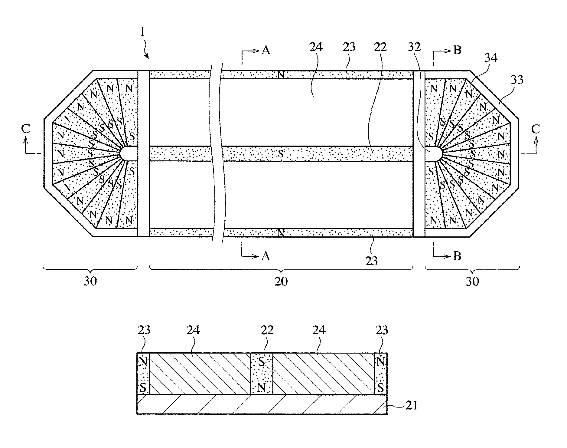
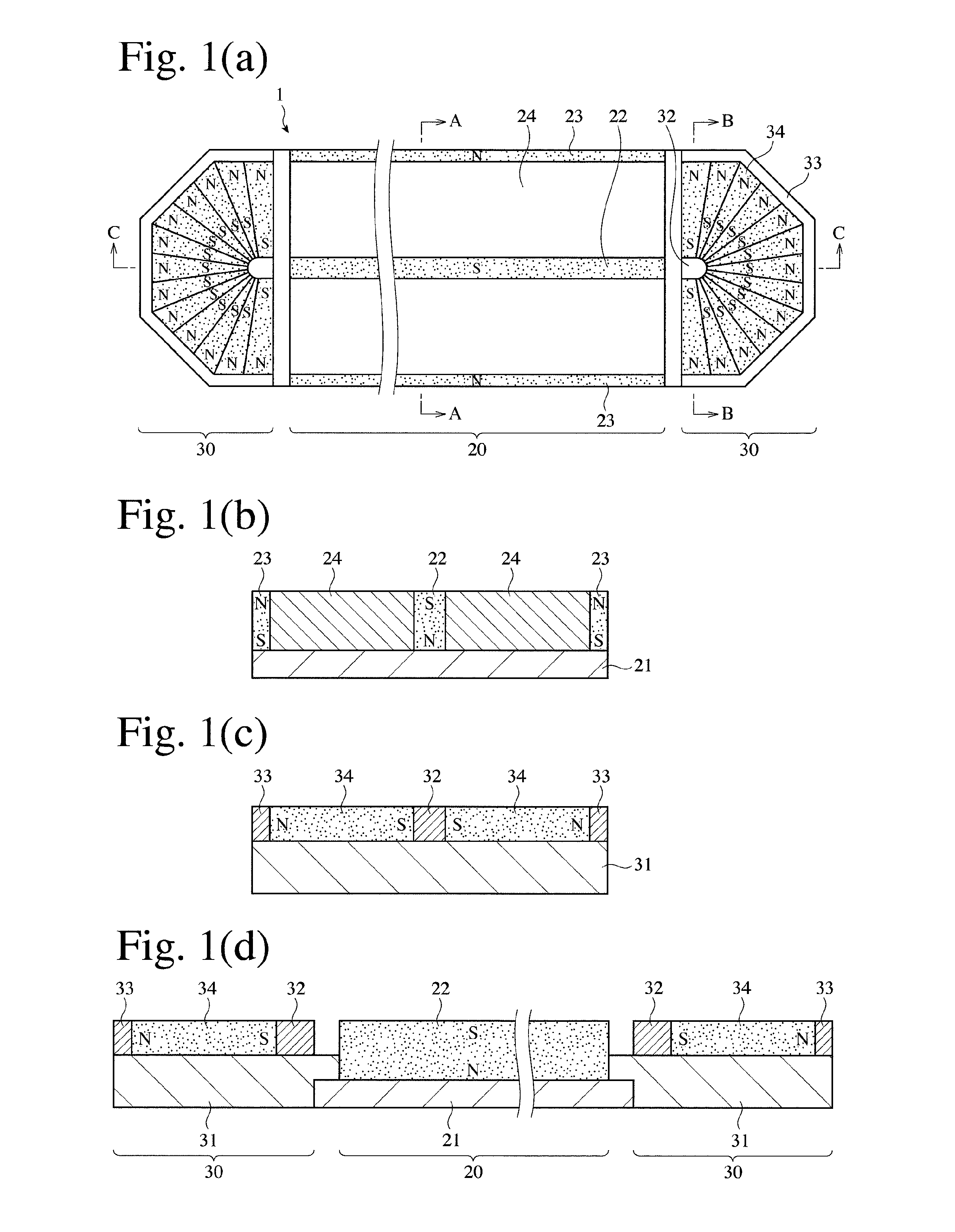
[0156]As shown in FIGS. 25(a), 25(b) and 25(c), a linear portion 20 comprising a yoke 21 formed by a steel plate (SS400), and a center permanent magnet 22 and side permanent magnets 23 formed by anisotropic sintered R-T-B magnets (NMX50AH available from Hitachi Metals, Ltd. having a maximum energy product of 50 MGOe or more), and corner portions 30 each comprising a base 31 made of austenitic stainless steel (SUS304), a center magnetic pole member 32 and a peripheral magnetic pole member 33 each formed by a steel plate (SS400), and permanent magnets 34 formed by anisotropic sintered R-TM-B magnets (NMX50AH available from Hitachi Metals, Ltd. having a maximum energy product of 50 MGOe or more) were assembled to produce a magnetic-field-generating apparatus 1, in which W=300 mm, L1=200 mm, L2=50 mm, a=100 mm, b=50 mm, c=20 mm, d=10 mm, e=30 mm, f=100 mm, g=50 mm, h=20 mm, i=10 mm, and j=10 mm. Horizontal and perpendicular components of a magnetic flux density at a height of 20 mm (cor...

example 2

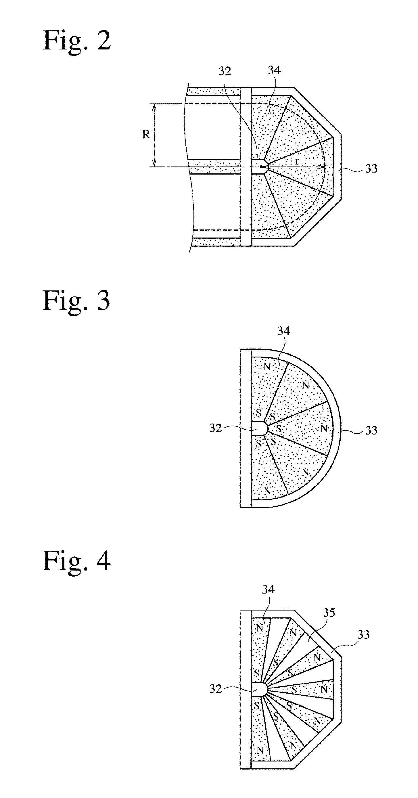
[0158]Points P and Q, at which a perpendicular component of a magnetic flux density on a target surface was zero, were measured along the lines A and D in the same manner as in Example 1, except for changing the arrangement of magnets in each corner portion as shown in FIG. 4 in the magnetic-field-generating apparatus 1 of Example 1 (see FIG. 25). The occupation ratio of magnets in the corner portion, which was a ratio of an area occupied by the permanent magnets to the area of space between the center magnetic pole member and the peripheral magnetic pole member, was 50%. In this structure, points P and Q were 37 mm and 43 mm, respectively, the same as in the magnetic-field-generating apparatus 1 of Example 1.

example 3

[0159]Points P and Q, at which a perpendicular component of a magnetic flux density on a target surface was zero, were measured along the lines A and D in the same manner as in Example 1, except for changing the arrangement of magnets in each corner portion as shown in FIG. 5 in the magnetic-field-generating apparatus 1 of Example 1 (see FIG. 25). The occupation ratio of magnets in the corner portion was 50%. In this structure, the points P and Q were 37 mm and 42 mm, respectively, substantially the same as in Example 1.


PUM

PropertyMeasurementUnit
magnetic flux densityaaaaaaaaaa
magnetic fieldaaaaaaaaaa
magnetic field intensityaaaaaaaaaa

Abstract

A racetrack-shaped magnetic-field-generating apparatus for magnetron sputtering comprising a linear portion and corner portions, the linear portion comprising a magnetic base, a center permanent magnet disposed on its surface, and side permanent magnets disposed on both sides thereof with a gap; the center and side permanent magnets being vertically magnetized with opposite polarities; the corner portions comprising a non-magnetic base, a center magnetic pole member disposed on its surface, a semicircular or semi-polygonal, peripheral magnetic pole member, and plural permanent magnets arranged between both magnetic pole members with their magnetization directions in parallel to a target surface; and the magnetic poles of plural permanent magnets opposing the center magnetic pole member having the same polarity as those of the center permanent magnet opposing the target.

Description

CROSS REFERENCE TO RELATED APPLICATIONS[0001]This application is a National Stage of International Application No. PCT / JP2012 / 050505 filed Jan. 12, 2012 (claiming priority based on Japanese Patent Application No. 2011-012315, filed Jan. 24, 2011, and No. 2011-038791, filed Feb. 24, 2011), the contents of which are incorporated herein by reference in their entirety.FIELD OF THE INVENTION[0002]The present invention relates to a magnetic-field-generating apparatus assembled in a magnetron sputtering apparatus for forming thin films on substrates.BACKGROUND OF THE INVENTION[0003]In the production process of electronic parts such as semiconductor ICs, etc., magnetron sputtering methods having high film-forming speeds by targets and capable of forming thin films at low temperatures because electrons are not impinged onto substrates are widely used to form thin films on substrates.[0004]A phenomenon that atoms or molecules are ejected from a target by a high-speed bombardment of an inert s...

Claims


Application Information

Patent Timeline
Patent Type & Authority Patents(United States)
IPC IPC(8): C23C14/34C23C14/35H01J37/34
CPCC23C14/351C23C14/35H01J37/3405H01J37/345H01J37/3408H01J37/3452H01J37/3461H05H1/46
Inventor KURIYAMA, YOSHIHIKOMITA, MASAHIRO
Owner HITACHI METALS LTD
Why Eureka
Try Eureka