Non-reciprocal circuit element

A technology of circuit components and components, applied in the field of non-reciprocal circuit components, can solve the problems of magnetic field leakage, circuit component influence, influence on the uniformity of magnetic field distribution, etc.

Inactive Publication Date: 2008-04-30
MURATA MFG CO LTD
View PDF9 Cites 0 Cited by
  • Summary
  • Abstract
  • Description
  • Claims
  • Application Information

AI Technical Summary

Problems solved by technology

[0009] And according to common non-reciprocal circuit elements, the air layer between the resin box 53 and the lower box 56 will generate a diamagnetic field, which affects the uniformity of the magn...

Method used


Image

  • Non-reciprocal circuit element
  • Non-reciprocal circuit element
  • Non-reciprocal circuit element

Examples


Embodiment Construction

[0033] Preferred embodiments of the invention are described below with the aid of the drawings.

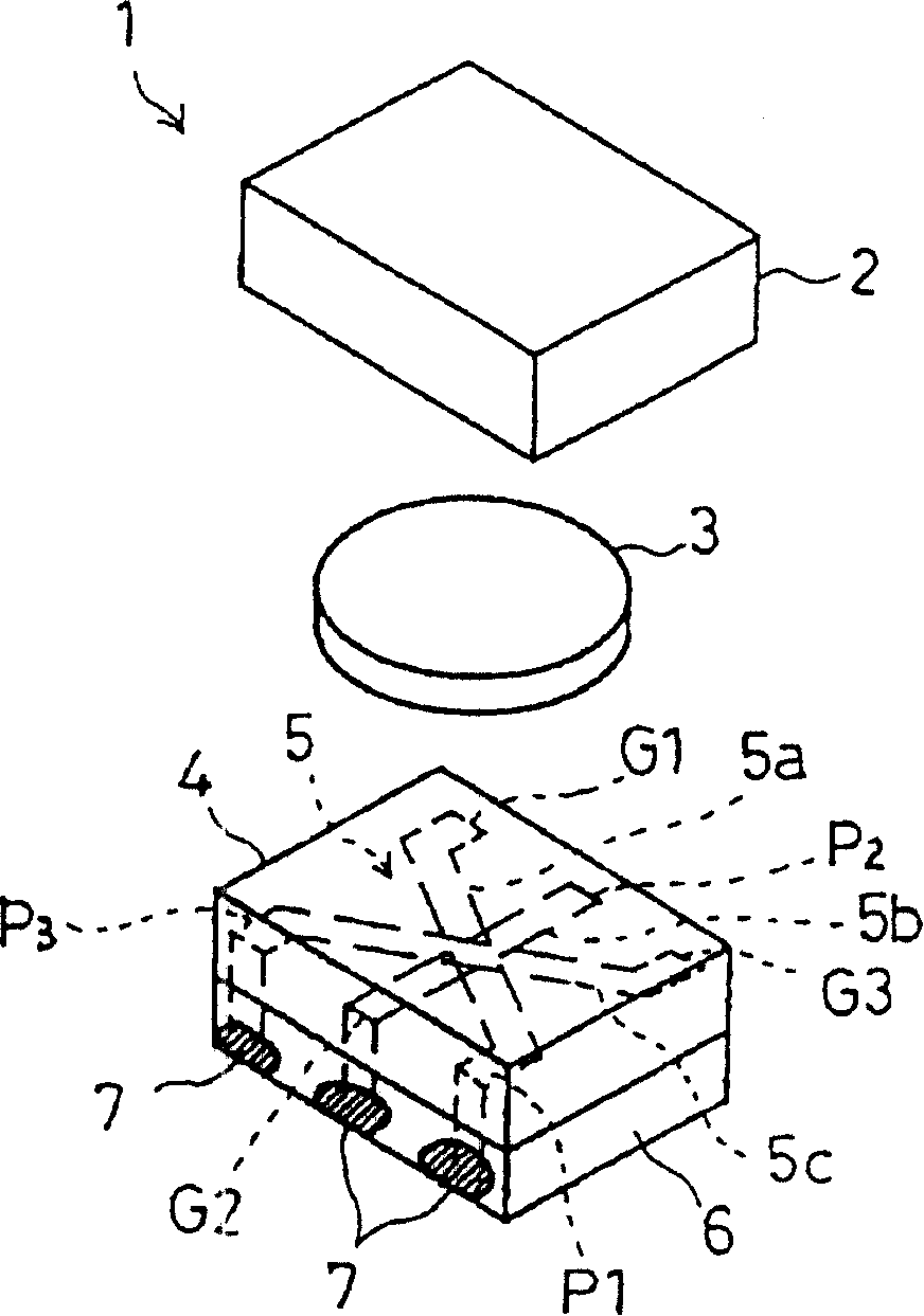
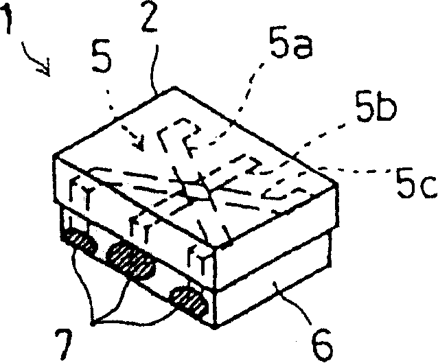
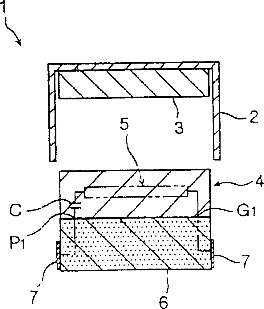
[0034] see Figure 1-3 , the lumped constant type gyrator 1 that represents the embodiment of the present invention includes box-shaped iron box 2, the disk-shaped permanent magnet 3 placed under the inner surface of the iron box 2 and the rectangular prism-shaped ferrite placed under the lower surface of the permanent magnet 3 Body 4. The DC magnetic field of the permanent magnet 3 is applied to a ferrite part 4 (eg yttrium iron garnet "YIG" or calcium barium garnet "CaBaG").

[0035] The ferrite part 4 includes an inner center electrode portion 5 . The center electrode portion 5 has a structure in which three electrode wires 5a-5c serving as inductive elements are arranged at an angle of 120 degrees to each other without being in electrical contact. Inside the ferrite member 4 is contained a matching capacitor electrode C connected to the input / output ports P1-P3 of the elect...


PUM


Abstract

The invention provides a nonreciprocal circuit element, comprising a ferrite component, a permanent magnet and a magnetic component, wherein, the ferrite component comprises a central electrode part inside which a plurality of electrode wires used as inductive elements are intersected at predetermined angles without electric contact; the ferrite component also comprises a matching capacitor electrode; the central electrode part and the matching capacitor electrode are formed on the surface of the ferrite component; the permanent magnet imposes a direct current magnetic field on the intersected position of the central electrode part; the magnetic part and any of the upper and the lower surfaces of the ferrite component form an integrated body; the magnetic part is made from magnetic material with the magnetic permeability bigger than that of the ferrite component.

Description

technical field [0001] The present invention relates to microwave electronic devices, and in particular to non-reciprocal circuit elements such as single-sided waveguides or gyrators. Background technique [0002] Lumped constant single-sided waveguides and gyrators for microwave bands have the ability to pass signals only in the desired direction of transmission and prevent them from passing in the opposite direction. For example, such devices are suitable for use in mobile communication devices such as portable telephone systems. [0003] Figure 15 and 16 An example of such a gyrator is shown. Figure 16 and 15 The configuration of the illustrated gyrator 50 is as follows. A resin block 53 embedded with a terminal 57 is placed on the lower surface of the ferrite member 52 . Three central electrodes 51a, 51b, 51c and matching capacitor electrodes (not shown) are contained in a ferrite part. And the permanent magnet 54 is placed on the upper surface of the ferrite par...

Claims


Application Information

Patent Timeline
IPC IPC(8): H01P1/32H01P1/36H01P1/383H01P1/387
CPCH01P1/387H01F1/10
Inventor 德寺博大平胜幸
Owner MURATA MFG CO LTD
Why Eureka
Try Eureka