

Rogowski coil
A Rogowski coil and bobbin technology, applied in the direction of transformer/inductor coil/winding/connection, preventing/reducing unnecessary electric/magnetic influence, etc., can solve the problem of increased magnetic field leakage and poor overall structural stability of Rogowski coils , Rogowski coil shape is difficult to maintain and other problems, to achieve the effect of improving accuracy, improving connection stability, and reducing magnetic field leakage
- Summary
- Abstract
- Description
- Claims
- Application Information
AI Technical Summary
Problems solved by technology
Method used
Image

Examples
Embodiment 1
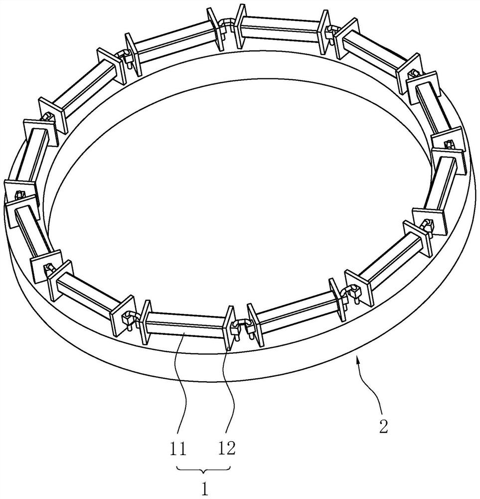
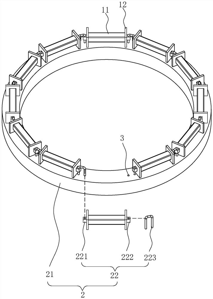
[0040] refer to figure 1 and figure 2 , the Rogowski coil includes a plurality of winding frames 1 and a limit mechanism 2, and the plurality of winding frames 1 are connected end to end, and the limit mechanism 2 includes a base 21 and a plurality of connecting components 22, and a plurality of winding frames 1 are arranged on the base 21 Above, the connecting assembly 22 makes the adjacent bobbins 1 hinged.
[0041] refer to figure 1 and figure 2 , The winding frame 1 includes a support rod 11 and two baffles 12, and the two baffles 12 are fixed at both ends of the support rod 11. In use, the coil is wound on the support rod 11, and the length of the coil is limited by the baffle 12. The connection assembly 22 includes a first connection block 221, a second connection block 222 and a latch 223. The first connection block 221 is integrally formed on the side of a baffle plate 12 away from the support rod 11, and the second connection block 6 is integrally formed on the ...
Embodiment 2
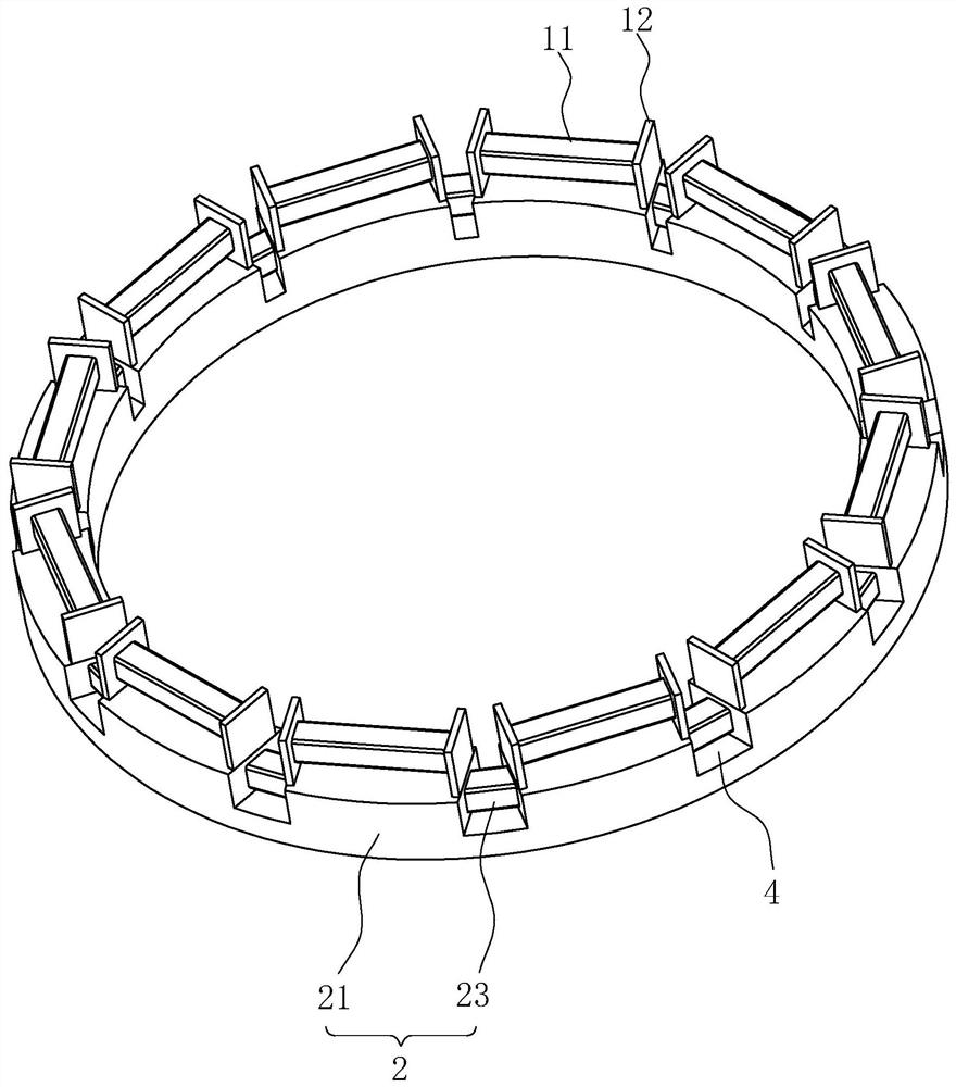
[0045] The difference between embodiment 2 and embodiment 1 is: refer to image 3 , The limit mechanism 2 includes a base 21 and a plurality of installation rods 23 , and the bobbin frame 1 is fixed on the base 21 . By fixing the winding frame 1 on the base 21, the stability of the connection between the winding frame 1 and the base 21 is improved, the stability between the winding frame 1 and the winding frame 1 is improved, and the leakage of the Rogowski coil magnetic field is reduced.
[0046] refer to image 3 , The base 21 is provided with a plurality of installation grooves 4, the installation grooves 4 are arranged between adjacent installation frames, and a plurality of installation rods 23 are arranged in the installation grooves 4 one by one. Wind the coil on the installation rod 23, use the coil on the installation rod 23 to fill the gap between the bobbins 1, and compensate the place where the magnetic field leaks more, so that the magnetic field of the Rogowski co...
Embodiment 3
[0049] The difference between embodiment 3 and embodiment 1 is: refer to Figure 4 , the limit mechanism 2 includes a plurality of mounting plates 24 and winding rods 25 arranged at intervals. The mounting plate 24 is integrally formed on the bottom surface of the baffle plate 12. The ends are integrally formed on the side walls of the two baffles 12 respectively, and the winding rod 25 is arranged between adjacent winding frames 1 . The winding frame 1 , the mounting plate 24 and the winding rod 25 are integrally formed to improve the stability between the winding frame 1 and the winding frame 1 and reduce the leakage of the Rogowski coil magnetic field. Due to the use of a printed circuit board, after the coil is wound, it can be directly welded on the printed circuit board, which facilitates and quickly completes the connection between the coils and improves the production efficiency of the Rogowski coil. The coil is wound on the winding rod 25 to compensate the places whe...
PUM
 Abstract
Description
Claims
Application Information