Cathode ray tube device that reduces magnetic field leakage

a cathode ray tube and magnetic field technology, applied in static indicating devices, snap-action devices, instruments, etc., can solve the problems of deteriorating deflection sensitivity, power consumption that is unnecessarily consumed, and second prior art that has another problem

Inactive Publication Date: 2002-08-15
PANASONIC CORP
View PDF0 Cites 0 Cited by
  • Summary
  • Abstract
  • Description
  • Claims
  • Application Information

AI Technical Summary

Benefits of technology

[0017] Therefore, it is a first object of the present invention to provide a CRT device that can prevent unnecessary power consumption and reduce a magnetic field leakage with a simple construction at low costs.
[0018] It is a second object of the present invention to provide a CRT device that can prevent unnecessary power consumption and reduce magnetic and electric field leakages with a simple construction at low costs.

Problems solved by technology

However, the CRT devices employing the techniques stated in the first and second prior arts respectively have the following problems.
Thus, power has to be unnecessarily consumed and, in addition to this, the deflection sensitivity may be deteriorated.
However, the second prior art has another problem.
However, the increased number of turns of the cancel coil 38 may in turn adversely affect the horizontal deflection magnetic field.
In. addition to this, the magnetic field leakage cannot be reduced using this technique.

Method used


Image

  • Cathode ray tube device that reduces magnetic field leakage
  • Cathode ray tube device that reduces magnetic field leakage
  • Cathode ray tube device that reduces magnetic field leakage

Examples


first embodiment

[0045] First Embodiment

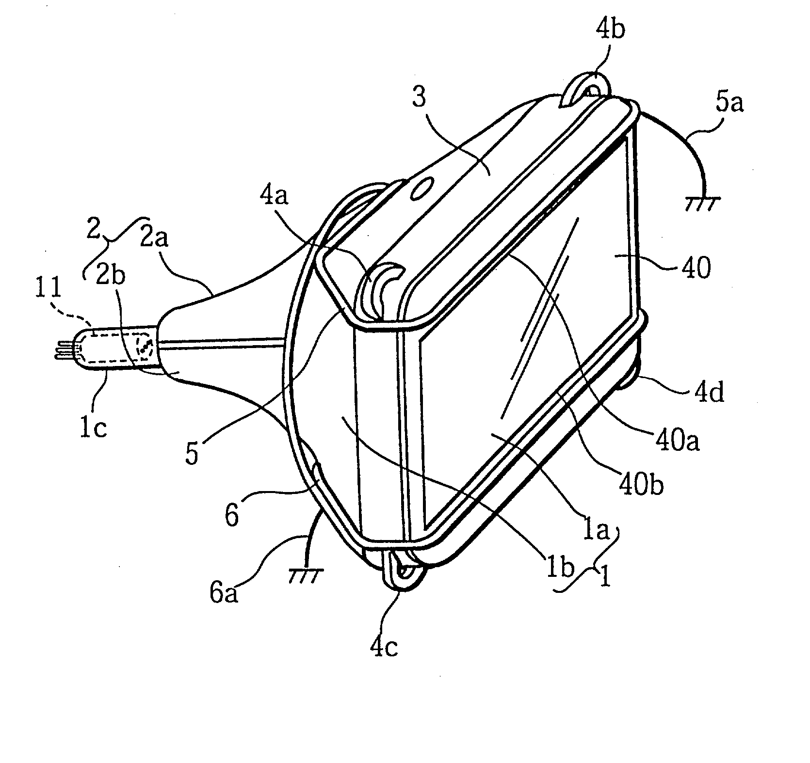
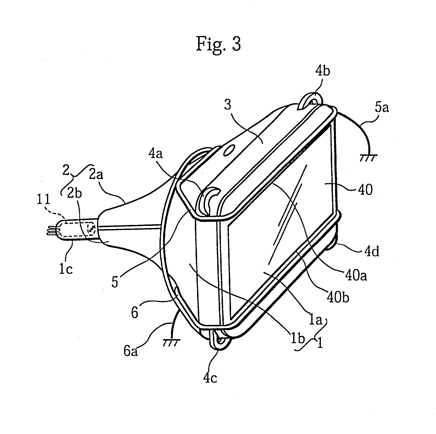
[0046] FIG. 3 is a perspective external view of a CRT device of the first embodiment of the present invention. FIG. 4 is a schematic front view of the CRT device while FIG. 5 is a rear view of the CRT device.

[0047] As shown in FIG. 3, the CRT device of the present embodiment is composed of a CRT 1, a deflection yoke 2, an electron gun 11, a reinforcing band (or, flameproof band) 3, a first closed-loop coil 5, and a second closed-loop coil 6. The CRT 1 is made up of a front panel 1a and a funnel 1b. The deflection yoke 2 is made up of an upper (the north pole side) horizontal deflection coil 2a, a lower (the south pole side) horizontal deflection coil 2b, a vertical deflection coil (not illustrated), and a core (not illustrated). The electron gun 11 is set inside a neck 1c. The reinforcing band 3 is set on the outer edge of the front panel 1a.

[0048] The reinforcing band 3 is usually made of metal, and is set so as to securely cover a connection part of the fron...

second embodiment

[0070] Second Embodiment

[0071] FIG. 10 is a perspective external view of a CRT device of the second embodiment of the present invention. The CRT device of the second embodiment is composed of a CRT 1, a deflection yoke 2, an electron gun 11, a reinforcing band (or, flameproof band) 3, and a closed-loop coil 5. The CRT 1 is made up of a front panel 1a and a funnel 1b. The deflection yoke 2 is made up of an upper horizontal deflection coil 2a, a lower horizontal deflection coil 2b, a vertical deflection coil (not illustrated), and a core (not illustrated). The reinforcing band 3 is set on the outer edge of the front panel la, and first to fourth ears 4a to 4d are respectively formed on the four corners of the reinforcing band 3.

[0072] The closed-loop coil 5 is set at an upper part of the CRT device. To be more specific, the closed-loop coil 5 is arranged just above a top edge 40a of an effective display region 40 of the front panel 1a. Simultaneously, the closed-loop coil 5 is arrange...


PUM


Abstract

Two closed-loop coils are respectively set at the top or the bottom of a cathode ray tube. These two closed-loop coils serves in a pair as a cancel coil. Each closed-loop coil is positioned so as to make an interlinkage with the magnetic field leakage that escapes from the deflection yoke, a part of the closed-loop coil running almost in parallel to the top or bottom edge of an effective display region of a front panel.

Description

[0001] (1) Field of the Invention[0002] The present invention relates to a cathode ray tube (CRT) device provided with a deflection yoke, and particularly relates to a technique for reducing a magnetic field escaping as leakage from the deflection yoke.[0003] (2) Related Art[0004] In recent years, the standards have been developed in Northern Europe in response to concerns about a low-frequency magnetic field given off by a CRT device. There is apprehension that such a-magnetic field may affect the human body. Especially in Sweden, the standards, such as the MPR II and TCO standards, have been established with the aim of suppressing the magnetic field escaping from a deflection yoke or a horizontal deflection coil in particular. The magnetic field escaping as leakage from the deflection yoke or the horizontal deflection coil is referred to as the "magnetic field leakage" hereinafter. To meet the leakage limits prescribed by the standards, necessary measures should be taken for the C...

Claims


Application Information

Patent Timeline
Patent Type & Authority Applications(United States)
IPC IPC(8): H01J29/00H01J29/76
CPCH01J29/003H01J2229/0015H01J29/76
Inventor UCHIDA, YUKIOIWAMOTO, TOMOAKIIWASAKI, KATSUYO
Owner PANASONIC CORP
Why Eureka
Try Eureka