Hybrid working machine

a working machine and hybrid technology, applied in the direction of machines/engines, electric generator control, electric devices, etc., can solve the problem of reducing the life of electric storage devices

Inactive Publication Date: 2008-04-24
KOBELCO CONSTR MASCH CO LTD
View PDF10 Cites 52 Cited by
  • Summary
  • Abstract
  • Description
  • Claims
  • Application Information

AI Technical Summary

Benefits of technology

[0015]It is an object of the present invention to provide a hybrid working machine capable of automatically stopping an assisting action in a state that engine assisting by a generator motor is not required.

Problems solved by technology

In this case, since wasteful consumption of stored power and over discharge are caused, it is not only unpreferable in view of saving energy, but also to decrease the life of the electric storage device.

Method used


Image

  • Hybrid working machine
  • Hybrid working machine
  • Hybrid working machine

Examples


Embodiment Construction

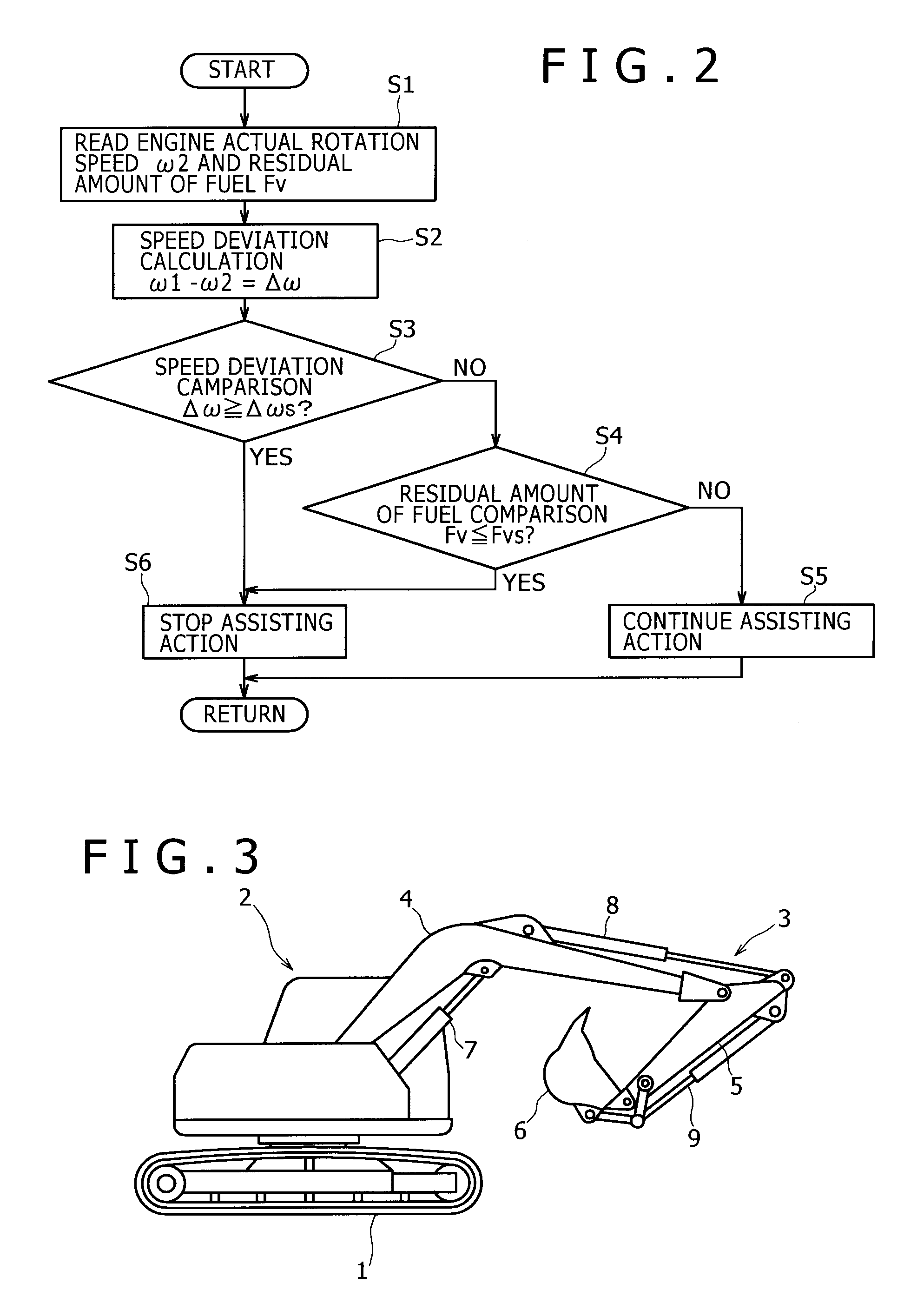
[0024]An embodiment of the present invention will be described with reference to FIGS. 1 and 2.

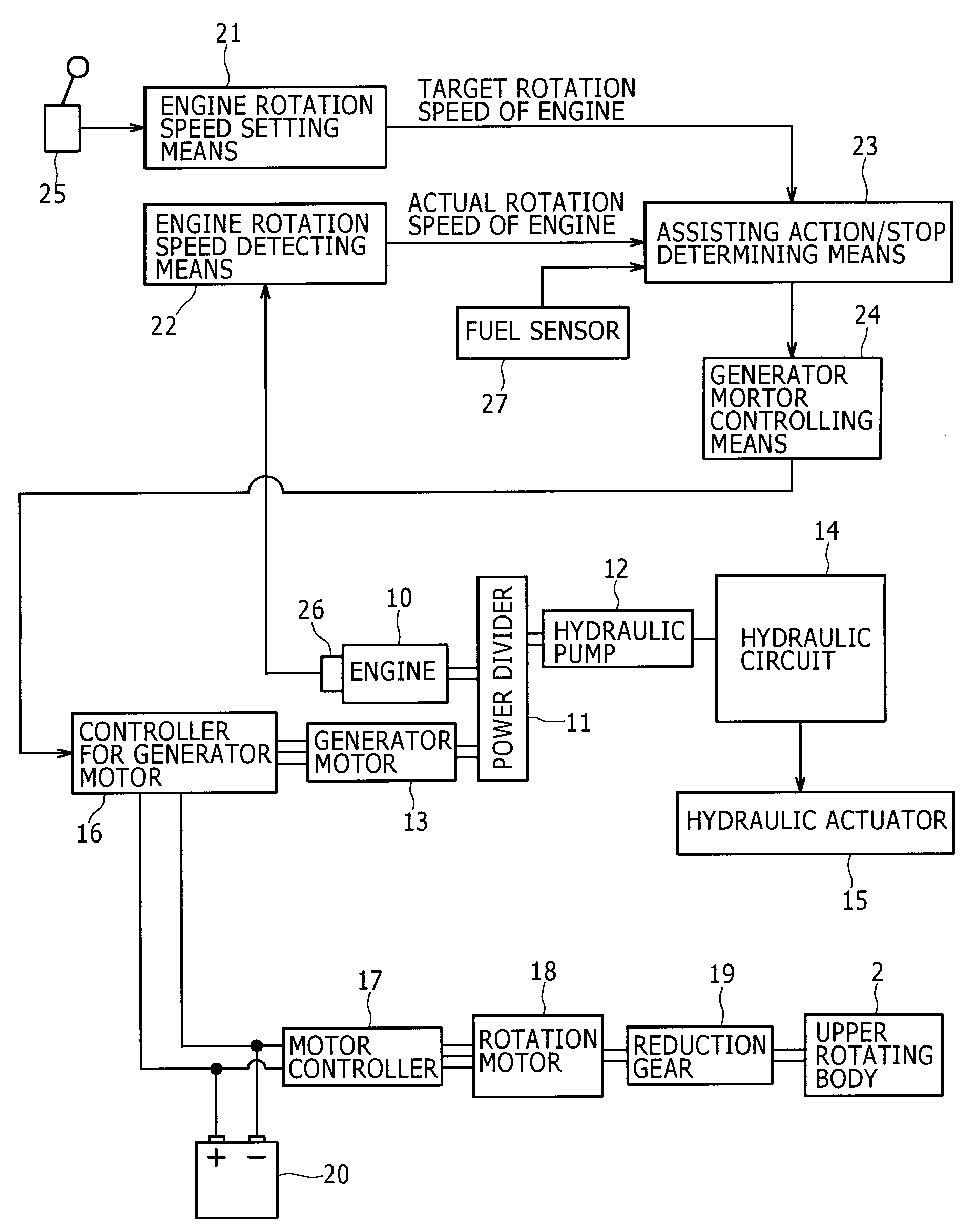
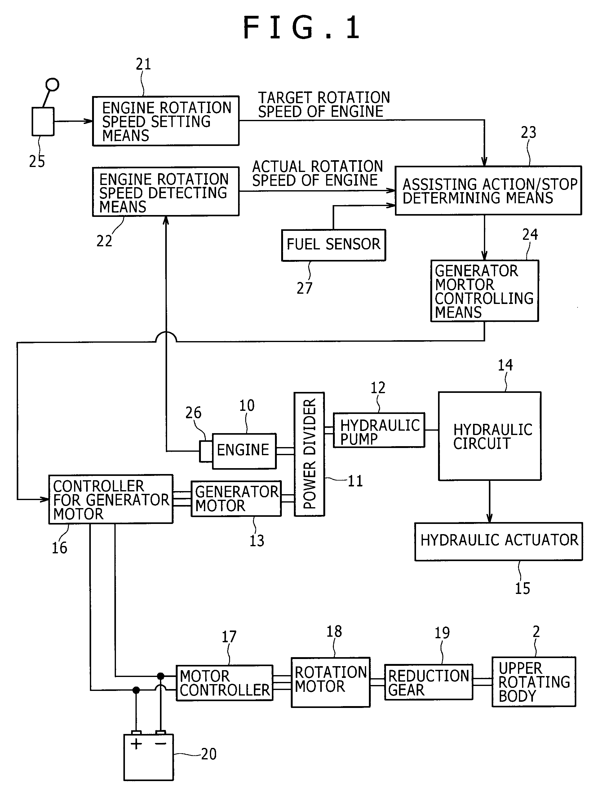
[0025]A block configuration of a hybrid excavator according to the embodiment will be shown in FIG. 1.

[0026]As shown in the figure, to an engine 10 are connected in parallel a variable capacity type hydraulic pump 12 and a generator motor 13 for performing a generator operation and a motor operation through a power divider 11. The hydraulic pump 12 and the generator motor 13 are driven by the engine 10.

[0027]A hydraulic circuit 14 is connected to the hydraulic pump 12, and hydraulic actuators (collectively given the reference numeral 15) including a boom cylinder 7 in FIG. 3 are driven by pressure oil from the hydraulic pump 12. It should be noted that although FIG. 1 shows the case where only one hydraulic pump 12 is connected, there is another case where a plurality of hydraulic pumps 12 are connected in parallel.

[0028]Power from the generator motor 13 is sent to a rotation motor 18 thro...


PUM


Abstract

The present invention is to drive a hydraulic pump and a generator motor by an engine, electrically charge a battery by a generator operation of the generator motor, and assist the engine through driving the generator motor by electric power of the battery. On the premise of the configuration above, when a deviation between a target rotation speed of the engine and an actual rotation speed of the engine is equal to or more than a preset value, and when a residual amount of fuel is equal to or less than a preset value, it is considered to be engine failure or an operation state which is directly connected to the engine failure and an engine assisting action is automatically stopped.

Description

BACKGROUND OF THE INVENTION[0001]1. Field of the Invention[0002]The present invention relates to a hybrid working machine using both engine power and electric power.[0003]2. Description of the Related Art[0004]The related art will be described taking an excavator which is a preferred example of the present invention as an example.[0005]The excavator is, as shown in FIG. 3, formed by rotatably mounting an upper rotating body 2 on a crawler type lower traveling body 1 and attaching a working attachment 3 to the upper rotating body 2.[0006]The working attachment 3 is formed of a boom 4 capable of raising and lowering, an arm 5 attached to an edge of the boom 4, a bucket 6 attached to an edge of the arm 5, and a boom cylinder 7, an arm cylinder 8 and a bucket cylinder 9 which are hydraulic actuators for driving the boom, the arm and the bucket.[0007]As a rotation actuator for rotating the upper rotating body 2, a hydraulic motor and a rotation motor serving as an electric actuator are u...

Claims


Application Information

Patent Timeline
Patent Type & Authority Applications(United States)
IPC IPC(8): F02D29/06H02P9/04B60L50/16
CPCB60K6/48B60L2250/24B60W10/06B60W20/00B60W2710/0644E02F9/2025E02F9/2075E02F9/2217Y02T10/6221B60L1/003B60L3/0023B60L11/14B60L11/1859B60L15/20B60L2200/40B60L2240/423B60L2240/441B60K6/543Y02T10/70Y02T10/72B60L50/16B60L58/14Y02T10/62Y02T10/64Y02T10/7072B60W20/50
Inventor KAGOSHIMA, MASAYUKIKOMIYAMA, MASAYUKI
Owner KOBELCO CONSTR MASCH CO LTD
Why Eureka
Try Eureka