
Alternating current generator having a plurality of independent three-phase windings

a technology of alternating current generator and three-phase winding, which is applied in the direction of windings, magnetic circuit rotating parts, magnetic circuit shape/form/construction, etc., can solve the problem of reducing the effective magnetic flux, and achieve the effect of reducing the noise of electromagnetic waves, increasing the cost and the size of products

Inactive Publication Date: 2004-03-16
DENSO CORP
View PDF28 Cites 19 Cited by
  • Summary
  • Abstract
  • Description
  • Claims
  • Application Information

AI Technical Summary

Benefits of technology

It is an object of the present invention is provide an a.c. generator, in which a magnetic noise is reduced and which generates a d.c. rectified output having a stabilized voltage, by reducing leakage magnetic flux occurring in an a.c. generator.
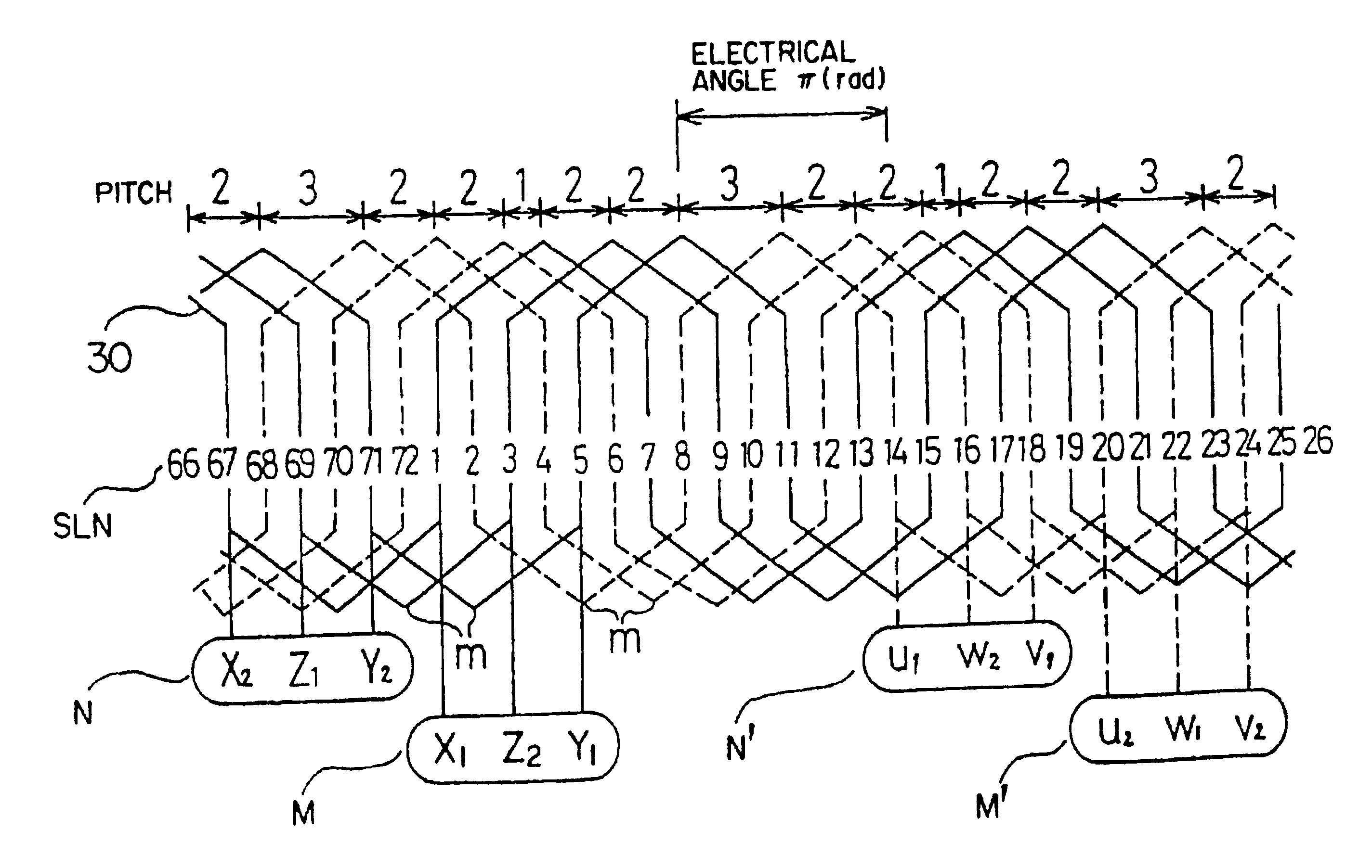
With such an arrangement, the distribution of a resultant magnetomotive force of each phase of the armature windings is shifted maintaining a non-varying shape, so that no large pulsating vibrational force is generated between the rotor and the stator. Therefore, an electromagnetic noise can be reduced, without giving rise to degradation of output performance and a rise in cost and in size of a product. Furthermore, no unbalanced circulating current is generated between the two sets of three-phase windings, so that both sets of three-phase windings can be connected in parallel with each other and further can be connected to a common three-phase rectifier.

Problems solved by technology

Such leakage of magnetic flux not only reduces the effective magnetic flux which contributes to electric power generation, but also generates pulsating magnetic flux.

Method used


Image

  • Alternating current generator having a plurality of independent three-phase windings
  • Alternating current generator having a plurality of independent three-phase windings
  • Alternating current generator having a plurality of independent three-phase windings

Examples


second embodiment

the present invention will be described with reference to FIGS. 11 to 13.

An a.c. generator is generally provided with a cooling fan radially inside of the coil ends of the armature windings projecting on both sides of the armature core (that is, radially inside of the portions of the three-phase armature windings projecting from slots of the armature core) so that the coil ends are forcibly cooled by an air flow produced by the fan.

However, the space between the fan and the coil ends is considerably narrow, so that the action caused by the air flow pressure generated by the fan upon the narrow space is apt to give rise to a fan noise. In particular, since the coil ends of the armature windings have a concave and convex shape having a predetermined pitch, a noise having a given audio frequency is generated.

It is desired in such a three-phase a.c. generator to prevent excessive congregation of coil ends as far as possible and to make constant the density of the arrangement of the coil...

fourth embodiment

the present invention will now be described.

Generally, there have been a three-phase a.c. generators having three-phase armature windings which are connected in Y-form or delta-form and which are wound concentratedly with full pitch on an armature core having three slots per one-pole pitch. With such a type of three-phase a.c. generator, even if a phase current flowing through each phase armature winding X, Y and Z is sinusoidal, the distribution of the air gap magnetomotive force remarkably fluctuates along the circumference of the rotor due to an influence of the third harmonic current contained in the armature current. Accordingly, the distribution of the air gap magnetomotive force is greatly distorted with the movement of a rotor in a rotational direction thereof, and, at the same time, the distribution of the air gap magnetomotive force fluctuates relative to the magnetic poles of the rotor. Therefore, there has been raised a problem that a noise is generated by the magnetic i...


PUM


Abstract

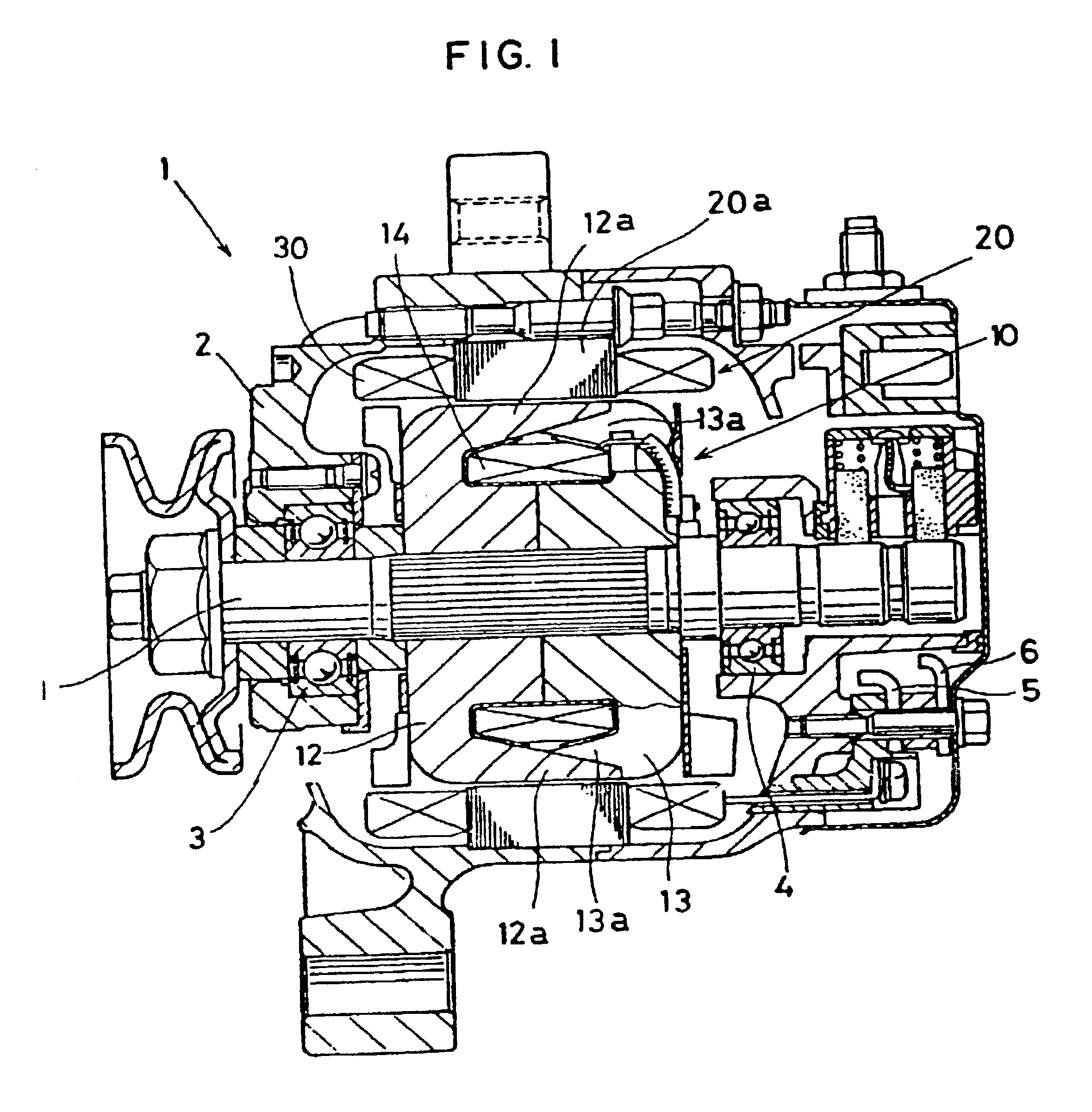
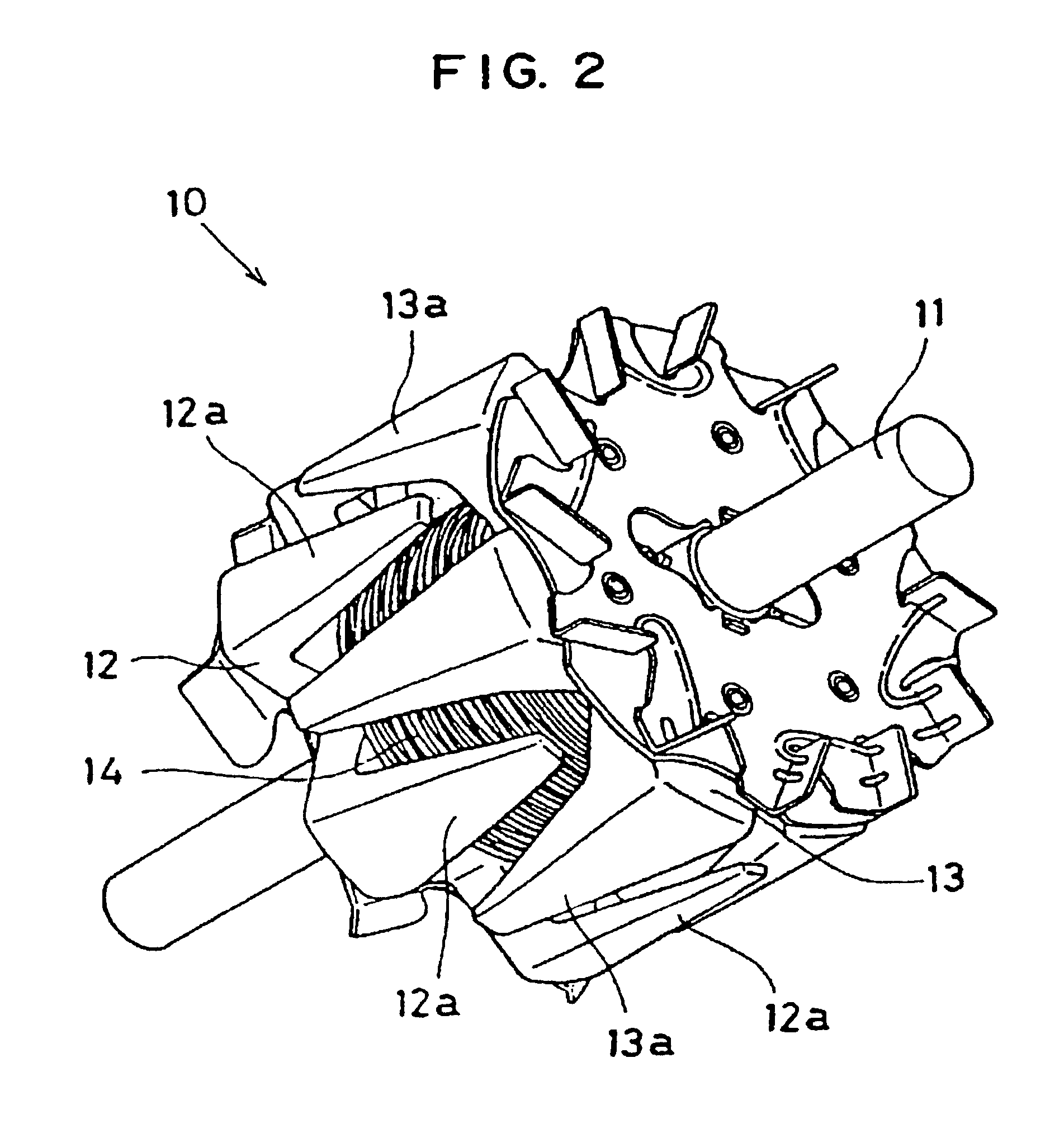
There is provided an alternating current generator comprising: a rotatably supported field rotor having a pair of opposed rotor pole cores, each being provided with P / 2 claw poles wherein P is an even number, and a field winding wound on the rotor pole cores; an armature core located around the outer periphery of the field rotor and having axially extending 3nP slots wherein n is an integer more than one; n independent sets of three-phase windings, each being wound on the armature core by being inserted in the slots so that the n sets of three-phase windings are shifted from each other by electrical angle of .pi. / (3n) radians; and three-phase rectifiers connected with the n sets of three-phase windings to rectify output voltages generated by the three-phase windings.

Description

BACKGROUND OF THE INVENTIONThe present invention relates to an alternating current generator having a plurality of sets of armature windings. More particularly, the alternating current generator of the present invention is suitable for use in a vehicle.There have been used an alternating current (hereinafter referred to as a.c.) generator for a vehicle in which a rotor having field windings is disposed inside a stator having three-phase windings.In this case, in order to increase the number of poles, a rotor is provided on the outer periphery thereof with a plurality of claw-shaped poles formed on a pair of magnetic cores. The armature of a stator is provided with 3 P slots (grooves) (one slot per phase and per pole) for the number of phases of the windings 3 and the number of poles P. The above-mentioned three-phase windings are disposed in these grooves and a tooth-shaped core is formed between a pair of neighboring slots or grooves.However, since the a.c. generator for a vehicle ...

Claims


Application Information

Patent Timeline
Patent Type & Authority Patents(United States)
IPC IPC(8): H02K3/28H02K19/34H02K19/22H02K19/16
CPCH02K3/28H02K19/22H02K19/34H02K2201/06
Inventor KUSASE, SINBANZAI, KEIICHIROHAYASHI, SEIJI
Owner DENSO CORP
Learn More