Protection device for load circuits

a protection device and load circuit technology, applied in the field of protection circuits, can solve the problems of circuits being forcibly shut down, not taking into account the effective rate of temperature increase, and smoke emission from the wire or the burning of the wire, so as to accurately perform the shutdown of the load circuit, accurately estimate the effect of the power shutdown and the effect of shutting down the load circui

Inactive Publication Date: 2007-11-01
YAZAKI CORP
View PDF22 Cites 61 Cited by
  • Summary
  • Abstract
  • Description
  • Claims
  • Application Information

AI Technical Summary

Benefits of technology

[0014]According to the above configuration, when the current measured by the current detection device would increase or be constant, the rising / increasing temperature of the conductor, including a wire and a contact conductor, can be estimated based on both the measured current and the thermal properties of the conductor. When the current detection device does not detect the current or detect the current decreases, the falling / decreasing temperature of the wire can be estimated based on the thermal properties of the conductor. Further, the arc-induced rising / increasing temperature is induced by the arcing that occurs when the current increases and then returns to the normal current. Furthermore, the present temperature of the wire can be estimated by use of the three estimated temperatures described above. If the present temperature of the wire exceeds the predetermined threshold value, the protection circuit determines that the wire could be burned out. If so, it will shut down the power of the load circuit. Accordingly, since this protection circuit's determination is derived from the estimated present temperature of the wire, the shutdown of the load circuit can be accurately performed.
[0015]Further, since the thermal resistance R and the heat capacity C of the conductor including the wire, which vary depending on the conductor, is used for the thermal properties for the above estimations, these four temperatures can be accurately estimated, so that it is possible to precisely control the shutdown of the load circuit.
[0016]Furthermore, since the estimations of the rising / increasing and the falling / decreasing temperatures of the wire may be estimated based on formulas which show heat generation and heat radiation of the conductor while taking into account the thermal resistance and the heat capacity thereof, the four temperatures can be accurately estimated, so that it is possible to more precisely control the shutdown of the load circuit.

Problems solved by technology

If a heating rate of the wire exceeds a cooling rate thereof, problems such as smoke emission from the wire or burnout of the wire may occur.
However, the protection apparatus for the load circuit as disclosed above determines whether the load circuit is shut down or not depending on cumulative heat of generated and radiated heat and it does not take into account an effective rate of increase of temperature.
Consequently, a problem would occur, in which the circuit would be forcibly shut down irrespective of the fact that power can still be applied to the load device.

Method used


Image

  • Protection device for load circuits
  • Protection device for load circuits
  • Protection device for load circuits

Examples


Embodiment Construction

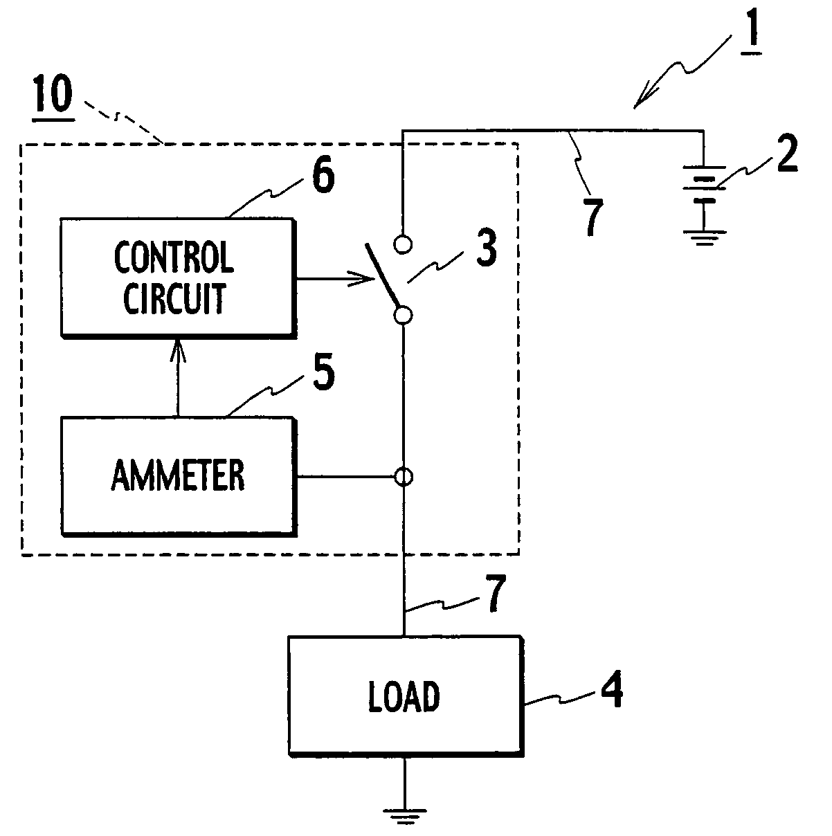
[0023]An embodiment of the present invention will be explained hereinafter with reference to the drawings. FIG. 1 is a circuit diagram of a load circuit in which a protection circuit is used. The load circuit may be used in a vehicle so that a battery provided in the vehicle to supplies power to a load, such as a bulb, a motor or the like.

[0024]As shown in the same figure, the load circuit 1 is provided between a battery 2 in a vehicle and a load 4, such as a bulb, a motor and the like. The load circuit 1 has an electrical switch (switch) 3 such as a MOSFET to supply power from the battery 2 to the load 4.

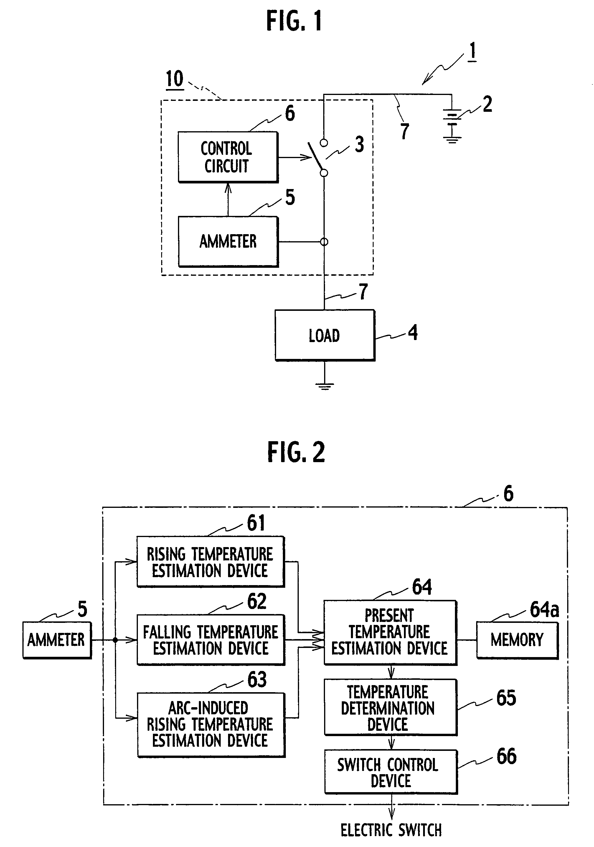
[0025]The load circuit 1 further has an ammeter (a current detection device) 5 for detecting and measuring a current flowing to the load 4, and a control circuit 6 for controlling ON and OFF states of the electrical switch 3. Here, the battery 2 is electrically connected to the electrical switch 3 by a wire 7. In the same way, the electrical switch 3 is electrically connected to th...


PUM


Abstract

A protection device protecting a load circuit by shutting off a power thereof depending on an estimated present temperature of a wire provided in the load circuit to connect a load. The protection device has a first temperature estimation device estimating a rising temperature of a conductor including the wire based on both a current in the conductor and thermal properties of the conductor, a second temperature estimation device estimating a falling temperature of the conductor based on the thermal properties, a third temperature estimation device estimating an arc-induced rising temperature of the conductor when arcing occurs in the conductor, and a fourth temperature estimation device estimating the present temperature of the conductor deduced from the above estimated temperatures. If the estimated temperature exceeds a predetermined allowable temperature, the protection device shut off the power of the load circuit.

Description

BACKGROUND OF THE INVENTION[0001]1. Field of the Invention[0002]The present invention is directed to a protection circuit for protecting a load circuit having a power supply, a switch, and a load. The protection device detects an increase of temperature of a conductive wire used therein.[0003]2. Description of the Related Art[0004]A conventional load circuit supplying power to a load such as a bulb, a motor or the like, has a battery and an electric switch (semiconductor switch, etc.) provided between the battery and the load. These components are connected by conductive wires. The load circuit further has a control device to turn on / off the electric switch. Specifically, the control device outputs a drive signal or a stop signal to the electric switch so that the load is driven or stopped.[0005]In the load circuit as described above, a protection function provided by a fuse or the like so as to shut down the power immediately when a current flowing in the load exceeds a predetermin...

Claims


Application Information

Patent Timeline
Patent Type & Authority Applications(United States)
IPC IPC(8): H02H5/04
CPCH02H7/228H02H6/005G01K3/005G01K7/42H01H2011/0068H01H2083/201H02H1/0015H02H5/04
Inventor NAKAMURA, YOSHIHIDEKANAZAWA, AKIYOSHI
Owner YAZAKI CORP
Why Eureka
Try Eureka