Hydraulic hand pump with pivoting links

a technology of pivoting links and hand pumps, which is applied in the direction of pumping devices, positive displacement liquid engines, suction devices, etc., can solve the problems of reducing the oil volume and pressure that can be delivered in the first stage, conventional hand pumps may or may not have locking devices, and inefficient use of direct-acting relief valves

Inactive Publication Date: 2007-11-01
SPX CORP
View PDF5 Cites 10 Cited by
  • Summary
  • Abstract
  • Description
  • Claims
  • Application Information

AI Technical Summary

Problems solved by technology

However, the use of the direct-acting relief valve is inefficient because during the second stage, every stroke of the hand pump requires additional effort by the operator to open the relief valve.
Additionally, using a direct-acting relief valve can decrease the oil volume and pressure that can be delivered in the first stage.
Further, conventional hand pumps may or may not have a locking device to lock down the handle.
Some handle locks may be awkward to use or prone to damage or misplacement because they are not integral with the pump.

Method used


Image

  • Hydraulic hand pump with pivoting links
  • Hydraulic hand pump with pivoting links
  • Hydraulic hand pump with pivoting links

Examples


Embodiment Construction

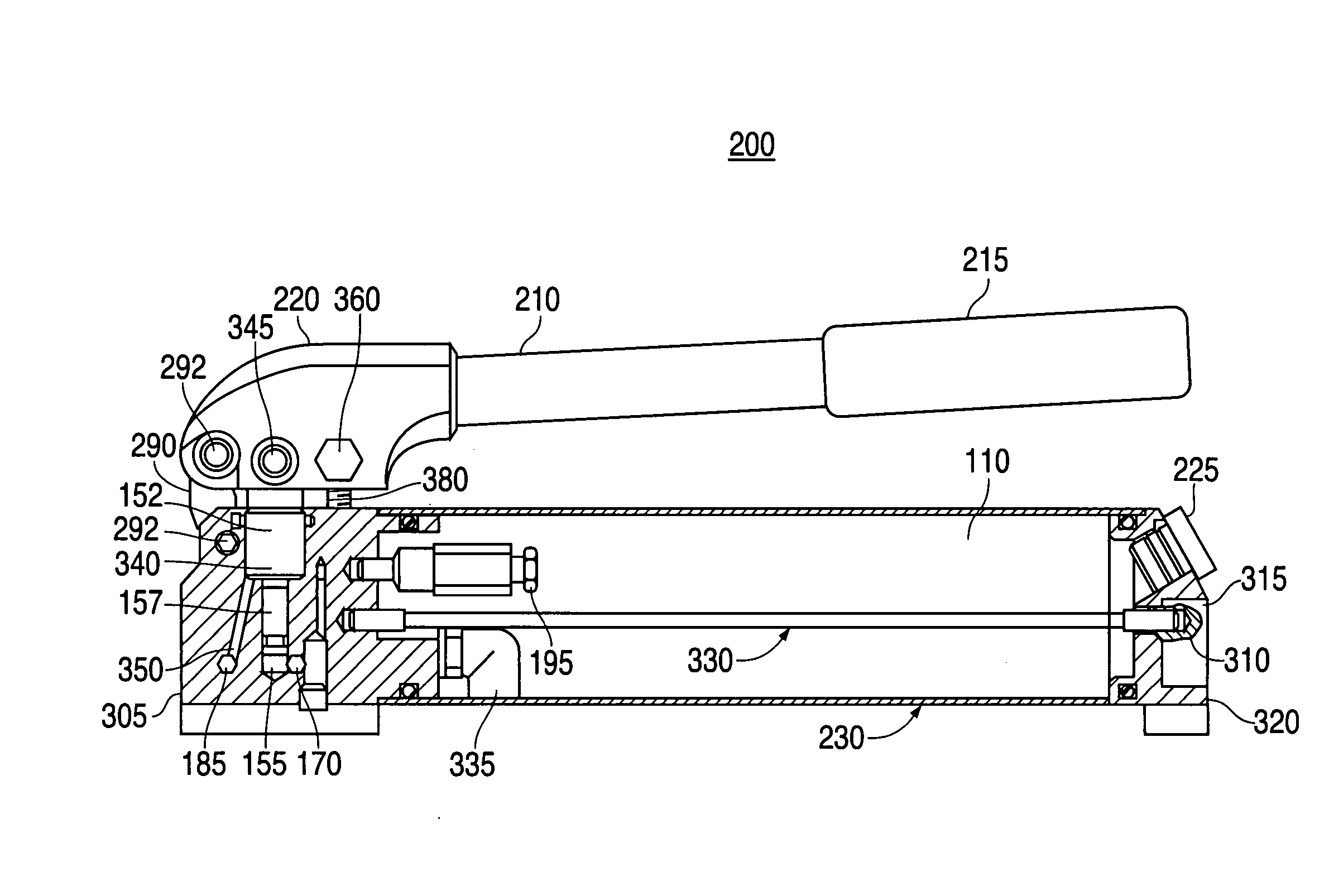
[0019] The invention will now be described with reference to the drawing figures, in which like reference numerals refer to like parts throughout. An embodiment in accordance with the present invention provides a hand pump having a handle locking mechanism, a counter bored nut, pivoting links, and unloading valve assembly. The unloading valve assembly allows a pump operator to pump a larger volume of hydraulic fluid and / or to pump to higher pressures in first stage operation than a conventional pump that employs a direct-acting relief valve. The unloading valve also decreases the effort required to pump the handle during the second stage operation. The handle locking mechanism allows the pump handle from moving during transporting and storing of the hand pump. The counter bored nut allows for more reservoir room than conventional hand pumps. The pivoting link allows for greater leverage of the handle during pumping.

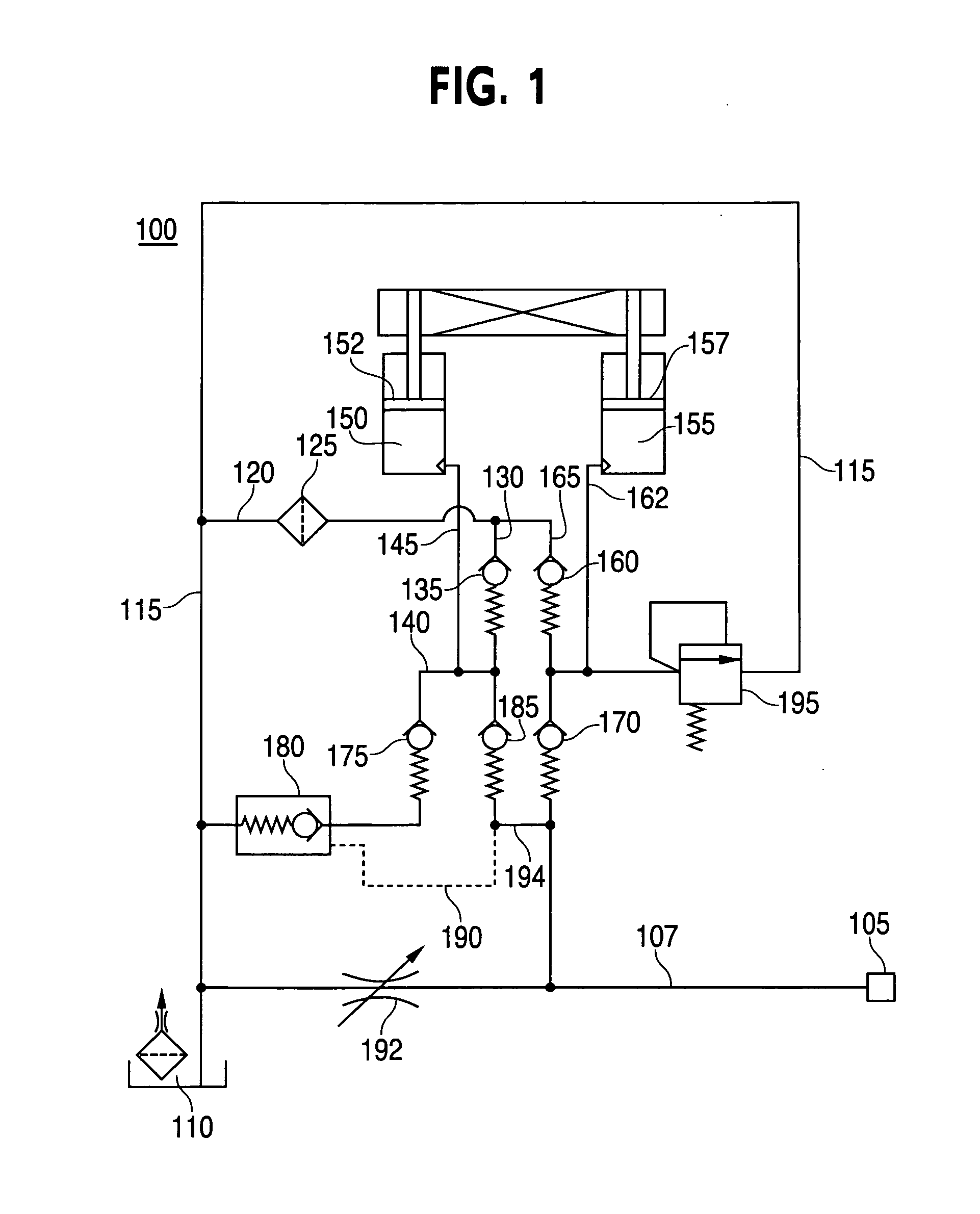
[0020]FIG. 1 is a hydraulic system schematic diagram 100 of a two-s...


PUM


Abstract

A method and apparatus is provided that includes a hand pump having a handle locking mechanism, a counter bored nut, pivoting links, and unloading valve assembly. The unloading valve assembly allows a pump operator to pump a larger volume of hydraulic fluid and / or to pump to higher pressures in first stage operation than a conventional pump which employs a direct-acting relief valve. The unloading valve also decreases the effort required to pump the handle during second stage operation. The handle locking mechanism allows the pump handle from moving during transporting and storing of the hand pump. The counter bored nut allows for more reservoir room than conventional hand pumps. The pivoting link allows for greater leverage of the handle during pumping.

Description

CROSS-REFERENCE TO RELATED APPLICATIONS [0001] This application claims priority to U.S. patent application entitled “Hydraulic Hand Pump,” filed Oct. 28, 2005, having a Ser. No. 11 / 260,185, which claims priority to provisional U.S. patent application entitled “Hand Pump with Unloading Valve,” filed Oct. 29, 2004, having a Ser. No. 60 / 622,798, the disclosures of which are hereby incorporated by reference in their entirety.FIELD OF THE INVENTION [0002] The present invention relates generally to a hydraulic hand pump. More particularly, the present invention relates to a hydraulic hand pump with pivoting links. BACKGROUND OF THE INVENTION [0003] Hand pumps containing hydraulic fluid are often used to pressurize hydraulic piston / cylinder assemblies in order to exert high forces on objects by pumping a handle on the pump. A piston / cylinder assembly can be attached to the hand pump to lift heavy objects, such as a vehicle. The hand pump includes an outlet that is connected to an inlet of ...

Claims


Application Information

Patent Timeline
Patent Type & Authority Applications(United States)
IPC IPC(8): A61M1/00
CPCF04B9/14
Inventor BAKKER, TRAVISLANDRUM, MICHAELMILLER, DOUGLAS
Owner SPX CORP
Why Eureka
Try Eureka