
System and method for optimizing throughput in a wireless network

a wireless network and throughput optimization technology, applied in the direction of network traffic/resource management, electrical equipment, selection arrangements, etc., can solve the problems of monopolizing the entire bandwidth or a significant portion of the bandwidth, severe reduction of the bandwidth available at fringe nodes, and significant disadvantage of the network association of fringe nodes

Inactive Publication Date: 2007-11-01
SYMBOL TECH INC
View PDF14 Cites 28 Cited by
  • Summary
  • Abstract
  • Description
  • Claims
  • Application Information

AI Technical Summary

Problems solved by technology

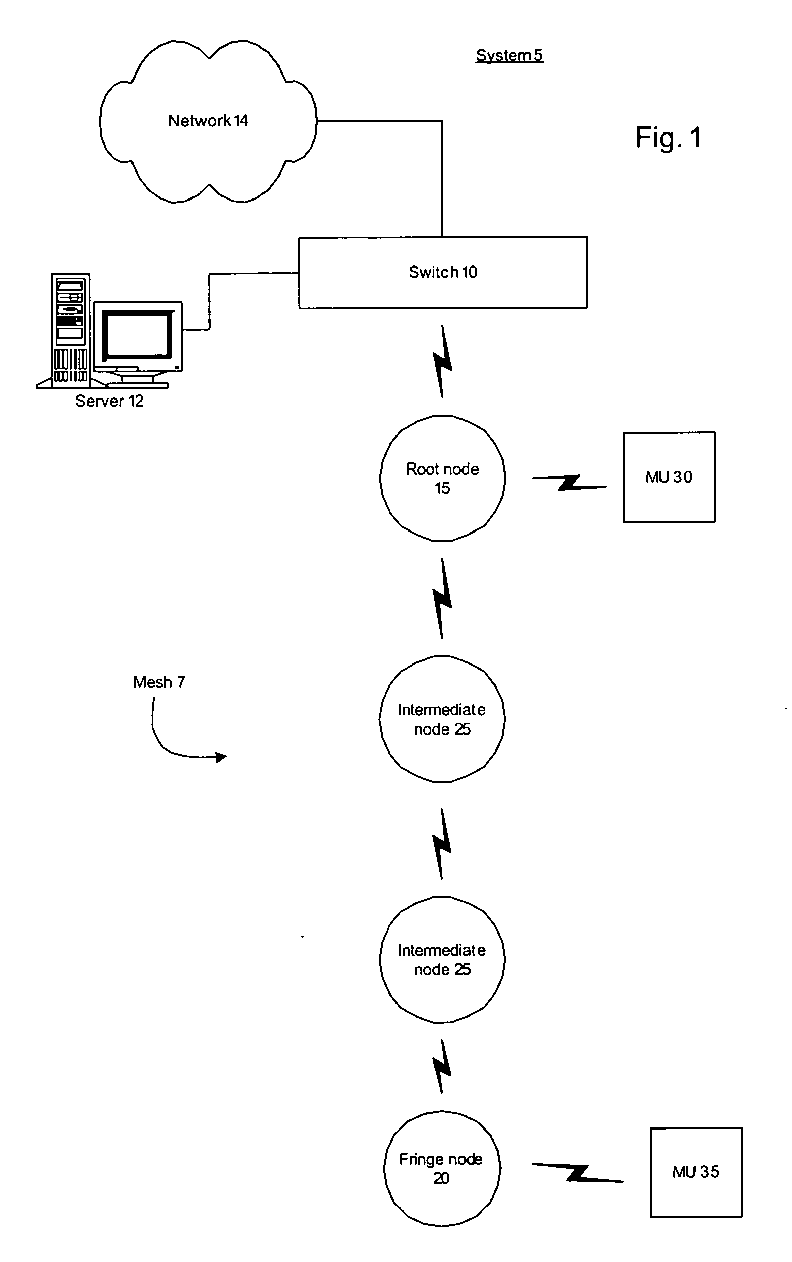
This may lead to a severe reduction in the bandwidth available at fringe nodes, which are separated from the root node by several intermediate nodes.
Thus, if those clients have a large amount of data to transmit, they may monopolize the entire bandwidth or a significant portion thereof.
Thus, the MUs associated with the fringe nodes are at a significant disadvantage in the network.
Adding to the problem is that traffic from the MUs associated with the fringe nodes exhibits an increased load relative to similar traffic from MUs associated with the intermediate nodes.
Because the traffic from the fringe node must go through several intermediate nodes and the root node before reaching the switch, a data rate at the fringe node is slower, resulting in latency and congestion in the mesh network.
Thus, in the conventional mesh network, the MUs associated with the root and intermediate nodes are granted an unfair high priority to the bandwidth in the mesh network.

Method used


Image

  • System and method for optimizing throughput in a wireless network
  • System and method for optimizing throughput in a wireless network
  • System and method for optimizing throughput in a wireless network

Examples


Embodiment Construction

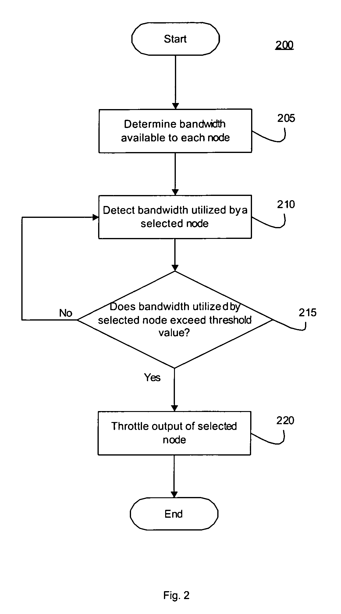
[0007] The present invention may be further understood with reference to the following description and the appended drawings, wherein like elements are provided with the same reference numerals. The present invention describes a system and method for optimizing throughput in a wireless network. While the exemplary embodiment of the present invention will be described with reference to a wireless mesh network and optimizing bandwidth available at nodes in the mesh, those of skill in the art will understand that the present invention may be utilized in any wireless environment in which distance from a root (e.g., server, mainframe, switch, etc.) has an effect on network conditions, e.g., bandwidth usage, latency, congestion, priority, etc.

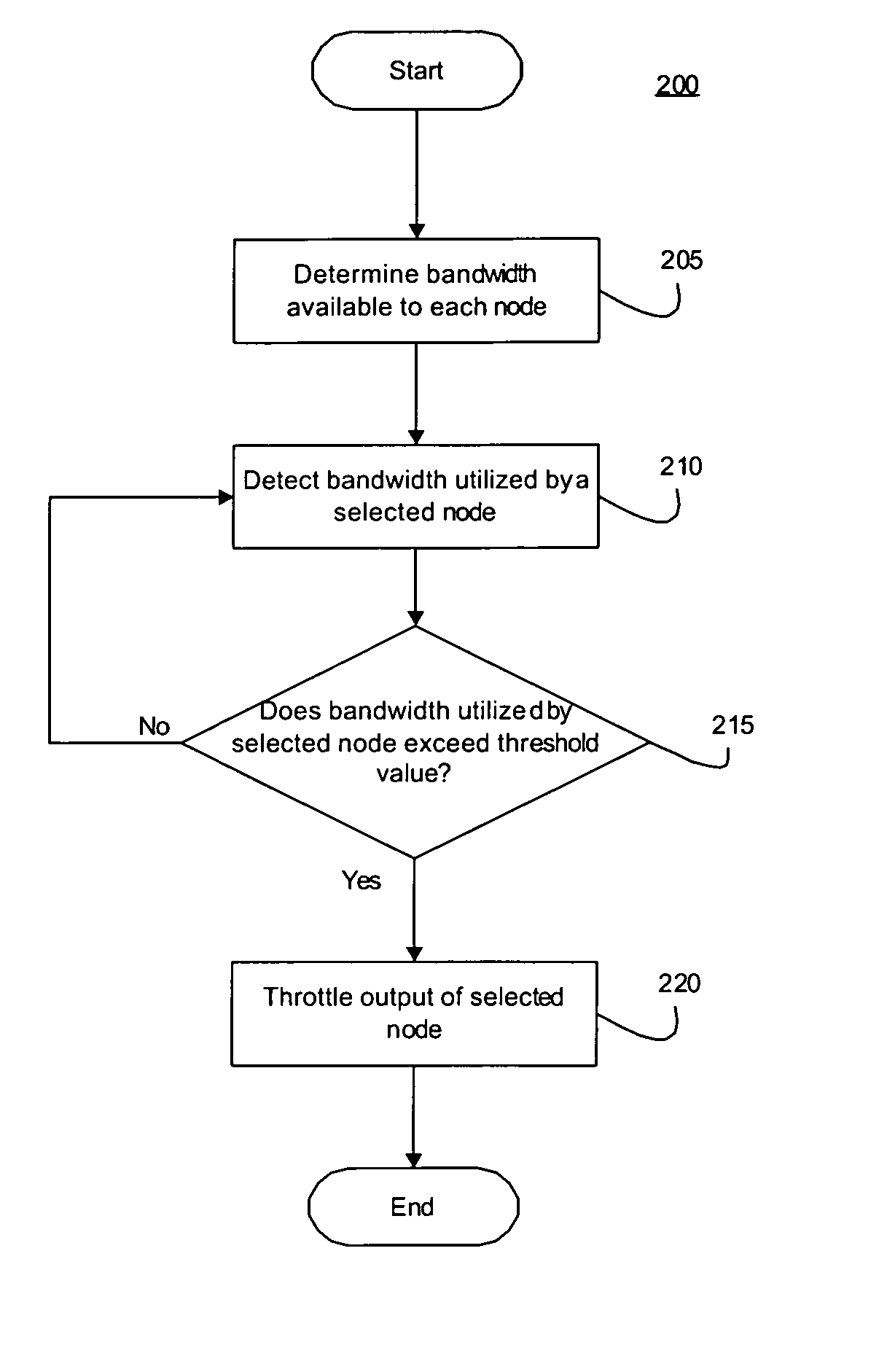
[0008]FIG. 1 shows an exemplary embodiment of a system 5 according to the present invention. The system 5 includes a wireless mesh 7 comprising a network management arrangement (e.g., a wireless switch 10) coupled to a plurality of mesh nodes which ...


PUM


Abstract

Described is a system and method for optimizing throughput in a wireless network. The method comprises providing a predetermined wireless bandwidth on a wireless communication channel to a plurality of wireless nodes. A bandwidth used by a selected wireless node is analyzed. When the bandwidth is outside of a predetermined threshold range, a predetermined action is executed to adjust the bandwidth utilized by the selected wireless node.

Description

FIELD OF INVENTION [0001] The present invention relates generally to measuring and controlling throughput in wireless environments. BACKGROUND [0002] In a conventional wireless mesh network, a bandwidth available at each mesh node decreases as a distance from a network management arrangement, e.g., a switch, increases. This may lead to a severe reduction in the bandwidth available at fringe nodes, which are separated from the root node by several intermediate nodes. For example, clients (e.g., mobile units (MUs)) associated with a root node (i.e., mesh node closest to the switch) may have access to the entire bandwidth. Thus, if those clients have a large amount of data to transmit, they may monopolize the entire bandwidth or a significant portion thereof. Any leftover bandwidth may then be utilized by MUs associated with the intermediates nodes. Thus, the MUs associated with the fringe nodes are at a significant disadvantage in the network. [0003] Adding to the problem is that traf...

Claims


Application Information

Patent Timeline
Patent Type & Authority Applications(United States)
IPC IPC(8): H04Q7/20H04W28/20
CPCH04W28/20
Inventor KAWAGUCHI, DEANLE, VINH-PHUONG TRA
Owner SYMBOL TECH INC
Learn More