
Monitoring and controlling applications executing in a computing node

a computing node and monitoring system technology, applied in computing, error detection/correction, instruments, etc., can solve the problems of insufficient code testing, insufficient protection against byzantine errors, and insufficient built-in sandboxing features of conventional process monitoring tools

Inactive Publication Date: 2007-11-01
KYNDRYL INC
View PDF11 Cites 10 Cited by
  • Summary
  • Abstract
  • Description
  • Claims
  • Application Information

AI Technical Summary

Benefits of technology

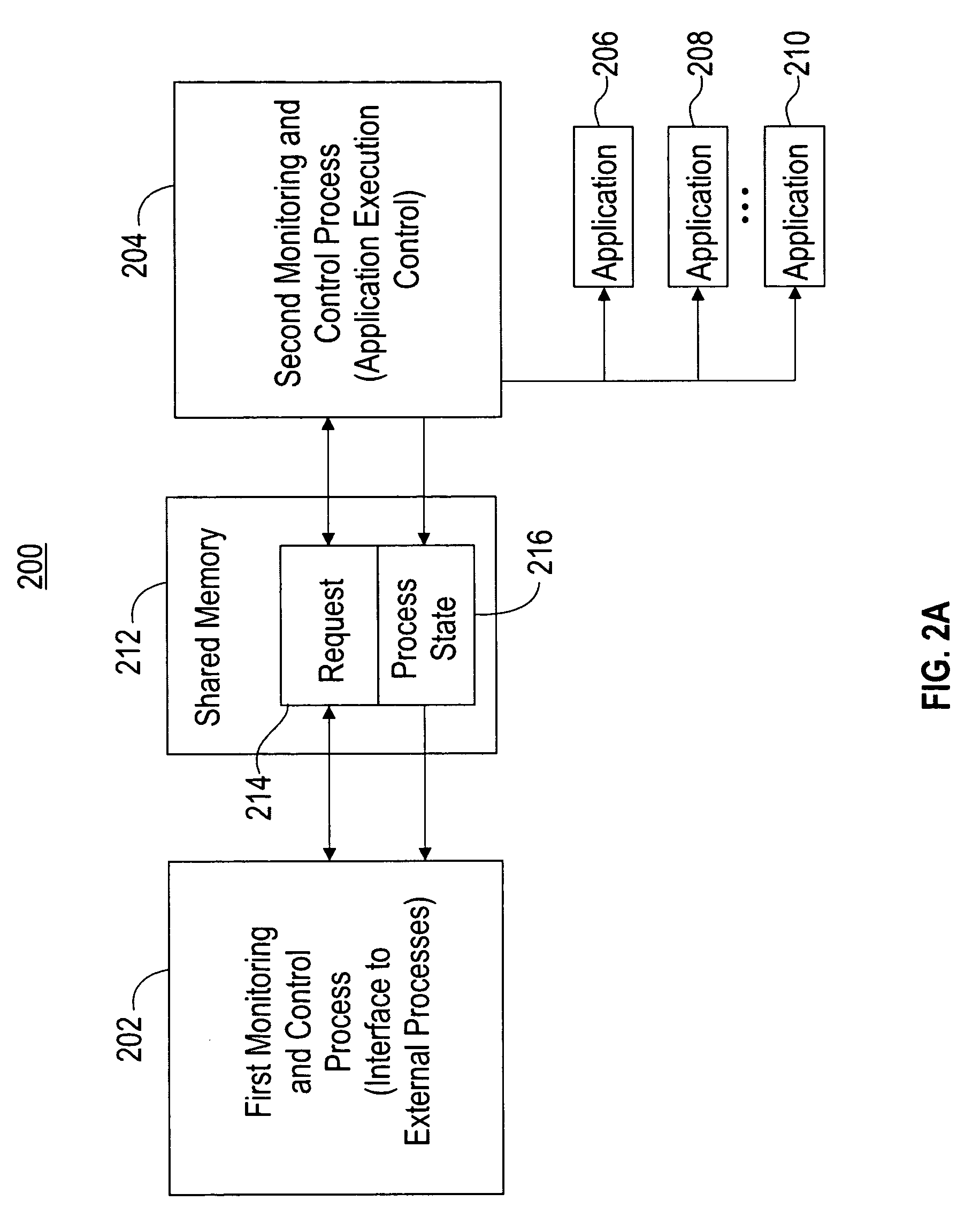
[0016] Advantageously, the present invention provides a technique for monitoring the status and performance, and controlling the execution of a plurality of applications on a computing node while isolating a failure of one of the applications (e.g., an untrusted application). The isolation of the failure allows the monitoring and controlling of the other applications to be preserved.

Problems solved by technology

Conventional process monitoring tools do not include adequate built-in sandboxing features to allow proper execution of unreliable code in a distributed or clustered computing system, where the code is not tested or not exhaustively tested.
Insufficient testing of code is commonplace in a text analytics platform such as the WebFountain cluster, due to the difficulty of simulating the complex computing environment.
Further, inadequately tested code in such a complex computing environment leads to Byzantine faults that are not sufficiently protected against by known monitoring tools.
A Byzantine fault is an arbitrary failure mode characterized by the erroneous, inconsistent and potentially malicious behavior of system components.
Still further, known monitoring tools do not ensure, in a programmatic manner, that a failure of an unreliable child application that causes the child's parent application to also fail does not adversely affect critical components in the rest of the computing system (e.g., by causing or facilitating a failure of other child applications of the failed parent application).

Method used


Image

  • Monitoring and controlling applications executing in a computing node
  • Monitoring and controlling applications executing in a computing node
  • Monitoring and controlling applications executing in a computing node

Examples


example 1

[0071] As one example of the monitoring and control process of FIG. 3, a configuration of computing node 240 is provided. In this example, each reference numeral corresponds to a reference numeral in FIG. 2C, but it will be understood that the steps of this example can also be implemented in the computing node configuration of FIG. 2A or FIG. 2B. Computing node 240 executes untrusted application 244 and one other application 246. It will be understood that the other application can also be a trusted application such as application 248 or 250. The steps of an execution of an application are included in Example 2 presented below. Second process 242-1 functions as the parent application to the untrusted application 244. As a parent application, second process 242-1 is capable of obtaining a status of application 244. Computing node 240 also executes first process (i.e., status request process) 202 and second processes (i.e., control processes) 242-1 and 242-2.

[0072] In this example, a...

example 2

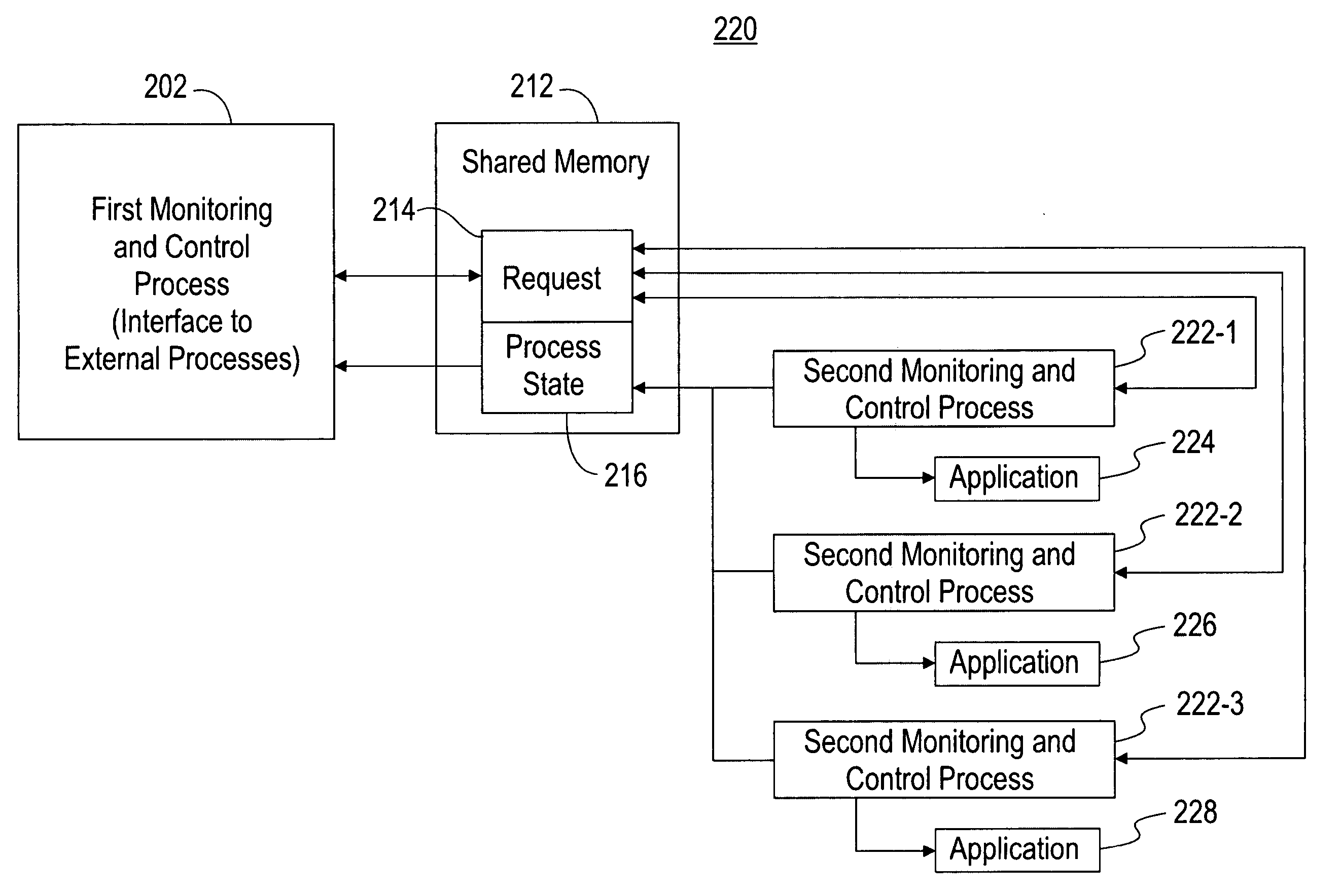
[0077]FIG. 4 is a flow chart of an exemplary process of executing an application on a computing node of FIGS. 2A, 2B or 2C, in accordance with embodiments of the present invention. In this example, reference numerals refer to components of FIG. 2B, and the application to be executed is application 224, but it will be understood that the steps in this example can also be implemented to execute an analogous application in the computing node configuration of FIG. 2A or FIG. 2C.

[0078] The application execution process begins at step 400. In step 402, first process 202 sends a start command message to second process 222-1 via request portion 214 of shared memory 212. The start command message indicates that an execution of application 224 is to be initiated. In step 404, second process 222-1 receives the start command message from request portion 214 of shared memory 212. In step 406, second process 222-1 utilizes a fork system to spawn off application 224. In step 408, second process 2...


PUM


Abstract

A method and system for monitoring and controlling applications executing on computing nodes of a computing system. A status request process, one or more control processes, an untrusted application and one other application are executed on a computing node. The status request process receives and processes requests for the statuses of the untrusted and the other application. A first control process controls the execution of the untrusted application. A second control process controls the execution of the other application. The execution of the untrusted application terminates based on a failure of the untrusted application. A capability of the status request process to receive and process the requests for statuses, and a capability of the second control process to control the execution of the other application are preserved in response to the termination of the untrusted application.

Description

BACKGROUND OF THE INVENTION [0001] 1. Technical Field [0002] The present invention relates to a method and system for monitoring and controlling applications executing in a computing node of a computing system, and more particularly to a technique for monitoring and controlling a plurality of applications in a computing node of a distributed computing system, where one or more applications of the plurality of applications are untrusted applications. [0003] 2. Related Art [0004] Conventional process monitoring tools do not include adequate built-in sandboxing features to allow proper execution of unreliable code in a distributed or clustered computing system, where the code is not tested or not exhaustively tested. Insufficient testing of code is commonplace in a text analytics platform such as the WebFountain cluster, due to the difficulty of simulating the complex computing environment. The WebFountain cluster is a large text analytics platform, which includes applications that pro...

Claims


Application Information

Patent Timeline
Patent Type & Authority Applications(United States)
IPC IPC(8): G06F9/44
CPCG06F11/1482G06F11/1438
Inventor BHAGWAN, VARUNGRUHL, DANIEL FREDERICK
Owner KYNDRYL INC
Learn More