Drive device and vehicle

a technology of a drive device and a drive shaft, which is applied in the direction of machines/engines, propulsion by batteries/cells, engine starters, etc., can solve the problems of unsatisfactory, likely degraded controllability of electric motors, so as to achieve high controllability, high controllability, and further degraded controllability of motors

Active Publication Date: 2018-04-19
DENSO CORP
View PDF5 Cites 7 Cited by
  • Summary
  • Abstract
  • Description
  • Claims
  • Application Information

AI Technical Summary

Benefits of technology

[0012]The drive device according to the first aspect may further include a rotation position detection sensor configured to detect a rotation position of a rotor of the motor, and a current sensor configured to detect a current flowing in the motor. The electronic control unit may be configured to determine that the high controllability is requested when an abnormality occurs in at least one of the rotation position detection sensor and the current sensor. When an abnormality occurs in the rotation position detection sensor or the current sensor, there is a possibility that the controllability of the motor is further degraded. Accordingly, when an abnormality occurs in at least one of the rotation position detection sensor and the current sensor, determination is made that the high controllability is requested, and the execution of the second PWM control as the control of the inverter is limited. With this, it is possible to sufficiently satisfy the request for the high controllability of the motor.
[0013]In the drive device according to first aspect, the electronic control unit may be configured to determine that the high controllability is requested when an amount of change per unit time of at least one of the torque command of the motor, a rotation speed of the motor, a voltage of the inverter, and a voltage of the electric power storage device is greater than a corresponding threshold. When the torque command or the rotation speed of the motor, the voltage of the inverter, or the voltage of the electric power storage device is rapidly changed (when a drive state of the motor is rapidly changed), there is a possibility that the controllability of the motor is further degraded. Accordingly, when the torque command or the rotation speed of the motor, the voltage of the inverter, or the voltage of the electric power storage device is rapidly changed, determination is made that the high controllability is requested, and the execution of the second PWM control as the control of the inverter is limited. With this, it is possible to sufficiently satisfy the request for the high controllability of the motor.
[0014]In the drive device according to the first aspect, the electronic control unit may be configured to determine that the high controllability is requested when vibration damping control by the motor is performed. When the vibration damping control by the motor is performed, in order to sufficiently exhibit vibration damping performance, the controllability of the motor may be further enhanced (is requested to be further enhanced). Accordingly, when the vibration damping control by the motor is performed, determination is made that the high controllability is requested, and the execution of the second PWM control as the control of the inverter is limited. With this, it is possible to sufficiently satisfy the request for the high controllability of the motor.

Problems solved by technology

However, in a case where the switching frequency of the switching elements is set to be small, controllability of the electric motor is likely to be degraded.
For this reason, there is a possibility that the controllability of the electric motor is further degraded for any reason or there is a request for further enhancing the controllability of the electric motor, and accordingly, there is a possibility that the request is not satisfied when high controllability of the electric motor is requested.
With the drive device of the first aspect, the execution of the second PWM control is limited when the high controllability of the motor is requested rather than when the high controllability is not requested.
Accordingly, the execution of the second PWM control as the control of the inverter is limited when the high controllability of the motor is requested rather than when the high controllability is not requested.
When the zero learning of the rotation position detection sensor or the current sensor is not completed, there is a possibility that the controllability of the motor is further degraded.
When an abnormality occurs in the rotation position detection sensor or the current sensor, there is a possibility that the controllability of the motor is further degraded.
When the torque command or the rotation speed of the motor, the voltage of the inverter, or the voltage of the electric power storage device is rapidly changed (when a drive state of the motor is rapidly changed), there is a possibility that the controllability of the motor is further degraded.
When an abnormality occurs in the current sensor or the voltage sensor, there is a possibility that the controllability of the motor is further degraded.
For this reason, there is a possibility that the controllability of the motor or the motor generator is further degraded.

Method used


Image

  • Drive device and vehicle
  • Drive device and vehicle
  • Drive device and vehicle

Examples


Embodiment Construction

[0034]Next, a mode for carrying out the present disclosure will be described in connection with an example.

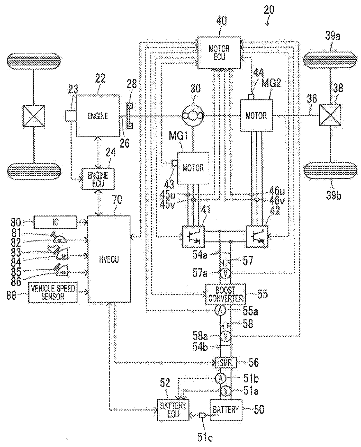
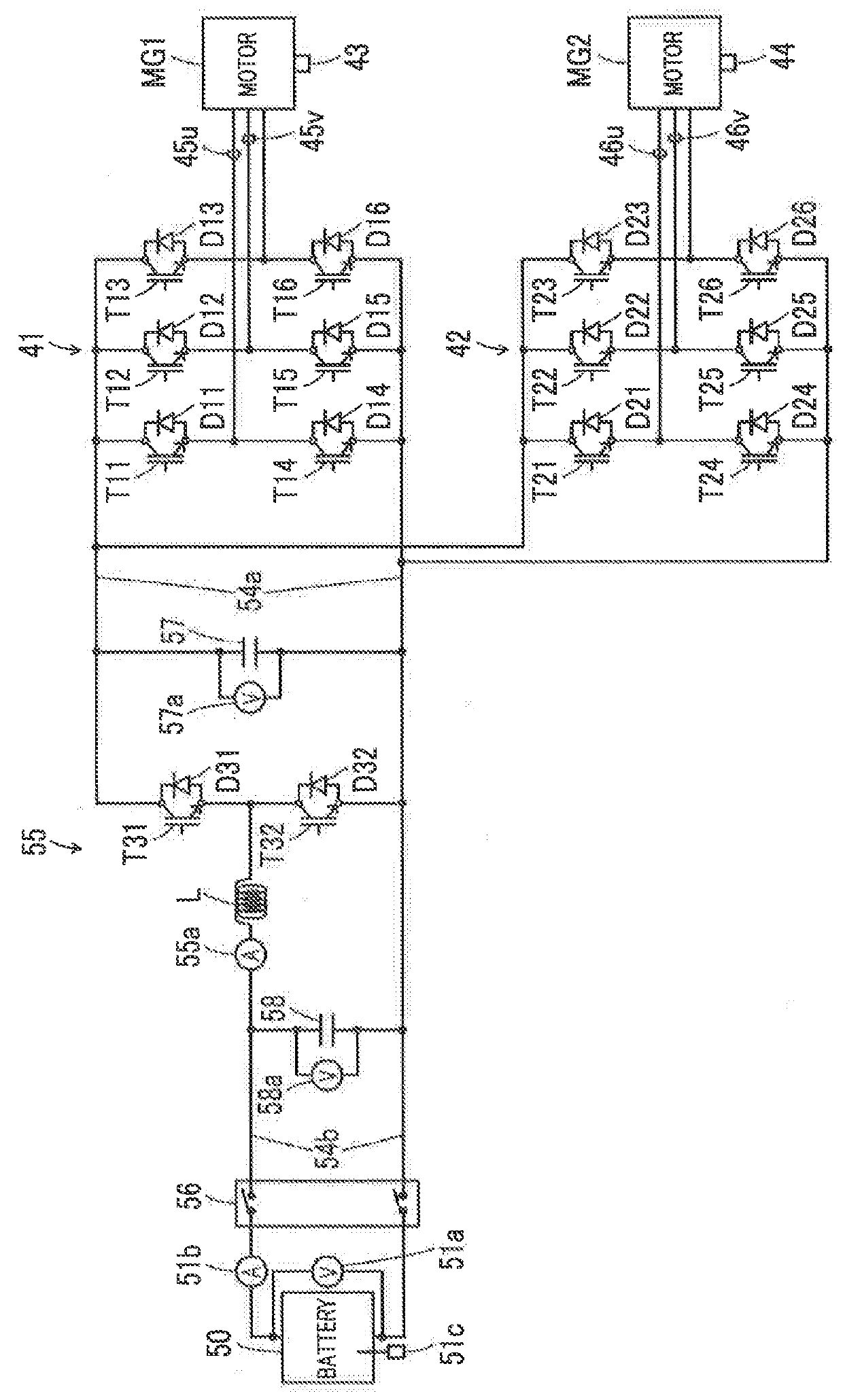
[0035]FIG. 1 is a configuration showing the outline of the configuration of a hybrid vehicle 20 in which a drive device as an example of the present disclosure is mounted. FIG. 2 is a configuration diagram showing the outline of the configuration of an electric drive system including motors MG1, MG2. As shown in FIG. 1, the hybrid vehicle 20 of the example includes an engine 22, a planetary gear 30, motors MG1, MG2, inverters 41, 42, a battery 50 as an electric power storage device, a boost converter 55, a system main relay 56, and an electronic control unit for hybrid (hereinafter, referred to as an “HVECU”) 70.

[0036]The engine 22 is constituted as an internal combustion engine that outputs power with gasoline, diesel, or the like as fuel. The engine 22 is operated and controlled by an electronic control unit for an engine (hereinafter, referred to as an “engine ECU”) 24.

[0037...


PUM


Abstract

A drive device includes a motor, an inverter, an electric power storage device, and an electronic control unit. The electronic control unit is configured to generate a first pulse width modulation (PWM) signal of the switching elements by comparison of a voltage command of each phase according to a torque command of the motor and a carrier wave voltage, as a first PWM control. The electronic control unit is configured to generate a second PWM signal of the switching elements based on a modulation factor and a voltage phase of a voltage according to the torque command and a pulse count per unit cycle of an electric angle of the motor, as a second pulse width modulation control. The electronic control unit is configured to limit execution of the second PWM control when high controllability of the motor is requested rather than when the high controllability is not requested.

Description

INCORPORATION BY REFERENCE[0001]The disclosure of Japanese Patent Application No. 2016-205427 filed on Oct. 19, 2016 including the specification, drawings and abstract is incorporated herein by reference in its entirety.BACKGROUND1. Technical Field[0002]The present disclosure relates to a drive device and a vehicle, and in particular, a drive device including a motor, an inverter, and an electric power storage device, and a vehicle in which the drive device is mounted.2. Description of Related Art[0003]In the related art, as a drive device, a drive device that includes an electric motor, and an electric power conversion device having an inverter circuit configured to drive the electric motor by switching a plurality of switching elements, generates a pulse signal of the switching elements based on a pulse count in one electrical cycle of the electric motor and a modulation factor and a voltage phase of a voltage according to a torque command of the electric motor, and switches the s...

Claims


Application Information

Patent Timeline
Patent Type & Authority Applications(United States)
IPC IPC(8): B60L15/20B60L15/00B60W20/10B60W20/40F02N11/08H02K7/116H02P6/28H02P6/04H02P27/08B60L50/15
CPCB60L15/20B60L15/007B60W20/10B60W20/40F02N11/0862H02K7/116H02P6/28H02P6/04H02P27/085B60L2210/14B60L2210/40B60L2240/427B60L2240/423B60K6/26B60K2006/268B60K6/445Y10S903/906B60L50/61H02P6/08F02N11/006F02N2300/104F02N11/04Y02T10/62Y02T10/64Y02T10/72
Inventor MATSUBARA, KIYOTAKAYAMADA, KENJIYAMAMOTO, TOSHIHIRO
Owner DENSO CORP
Why Eureka
Try Eureka