Transforaminal lumbar interbody fusion cage

a transforaminal lumbar and interbody technology, applied in the field of orthopedic surgery, can solve the problems of difficult prior art interbody fusion cages requiring considerable space to be rotated, etc., and achieve the effect of facilitating the insertion of fusion cages and reducing the space necessary for the insertion of cages

Inactive Publication Date: 2007-11-08
BIYANI ASHOK
View PDF21 Cites 143 Cited by
  • Summary
  • Abstract
  • Description
  • Claims
  • Application Information

AI Technical Summary

Benefits of technology

[0005]The present invention relates to a fusion cage that is used to separate and support adjacent vertebrae in the spine. The fusion cage may be designed for use in the lumbar region of the spine, although it is possible to use the fusion cage of the present invention in other areas of the spine as well. The fusion cage has a first spacer member or chamber and a second spacer member or chamber that are pivotally interconnected by an articulating mechanism such as a hinge. The first and second spacer members are designed for insertion between adjacent vertebrae to properly support and separate the vertebrae. An advancing mechanism is located between the first and second spacer members to pivotally move the first spacer member relative to the second spacer member around the hinge. The angular position of the first spacer member relative to the second spacer member facilitates the insertion of the fusion cage around the dural sac and reduces the space necessary for the insertion of the cage. The advancing mechanism is operable to adjust the angular position of the first and second spacer members so that the first and second spacer members are in the desired position relative to the adjacent vertebrae when the cage is fully inserted.

Problems solved by technology

However, in inserting such fusion cages using minimally invasive surgical techniques, it is oftentimes difficult to insert a fusion cage without making an incision that is larger than desired or significantly displacing the neural element.
Typically, interbody fusion cages of the prior art require considerable space to be rotated into the proper position between adjacent vertebrae.

Method used


Image

  • Transforaminal lumbar interbody fusion cage
  • Transforaminal lumbar interbody fusion cage
  • Transforaminal lumbar interbody fusion cage

Examples


Embodiment Construction

)

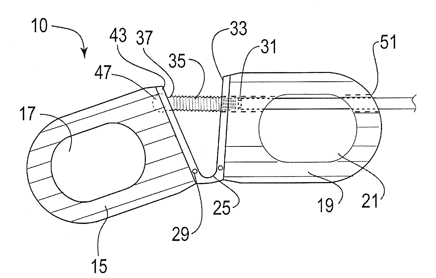
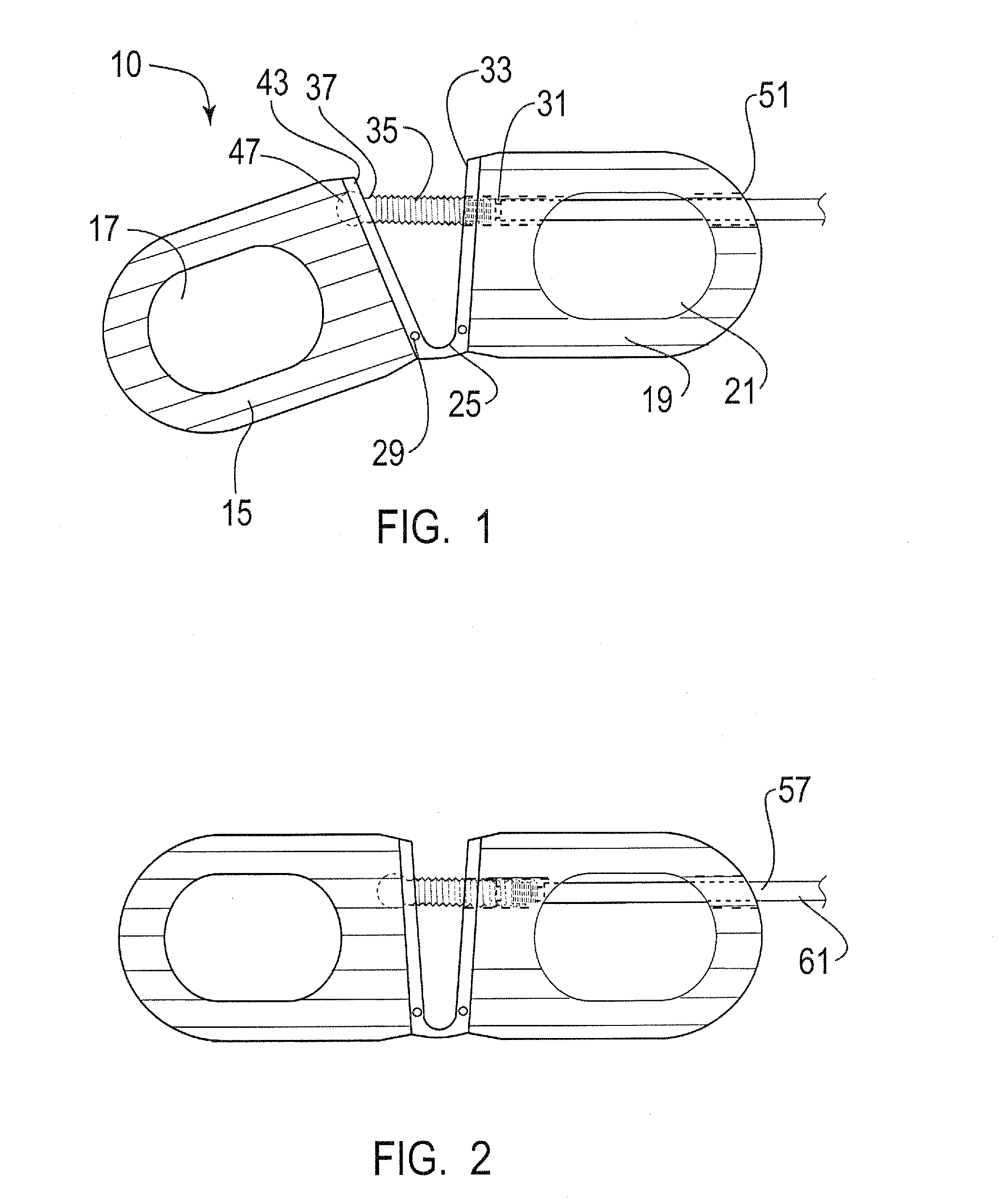
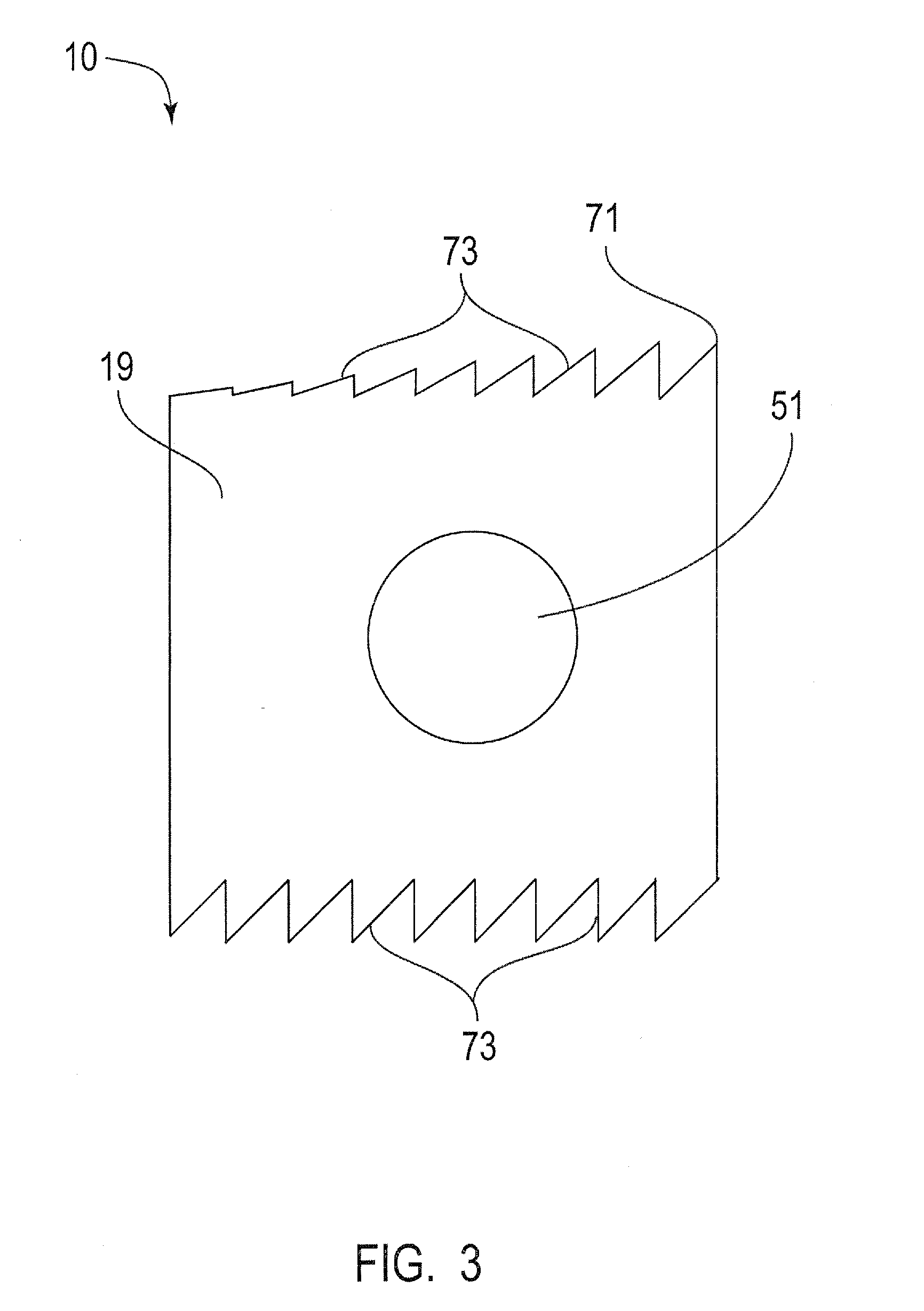
[0011]The present invention is directed to an interbody fusion cage that is used in spinal fusion procedures, such as a transforaminal lumbar spinal fusion procedure, by way of example. More particularly, the present invention is directed to an articulated fusion cage that can be adjusted in configuration to facilitate the insertion of the cage between adjacent vertebrae in the spine, such as the lumbar region. The fusion cage of the present invention may be inserted by the use of minimally invasive surgical techniques wherein relatively small incisions are made in the patient and instruments are utilized to guide the cage to the desired location between adjacent vertebrae. The articulated nature of the cage allows the cage to be disposed at an angle that facilitates the insertion of the cage around the neural elements and reduces the displacement or impact on the nerve roots during the insertion process.

[0012]Referring now to the figures, and to FIGS. 1-2 in particular, the fusion...


PUM


Abstract

A cage to separate and support adjacent vertebrae in the spine that have undergone orthopedic spinal fusion procedures. The cage has first and second spacer members for insertion between adjacent vertebrae with a hinge located between the spacers. An advancing mechanism is located between the first and second spacer members that pivotally moves the first and second spacer members relative to each other at an angle which facilitates the insertion of the cage around the spinal cord. After insertion, the advancing mechanism is operable to position the first and second spacer members in the desired position between the two adjacent vertebrae.

Description

[0001]The present application claims the filing benefit of U.S. Provisional Application Ser. No. 60 / 796,691, filed May 2, 2006, the disclosure of which is hereby incorporated herein by reference in its entirety.FIELD OF THE INVENTION[0002]The present invention relates generally to the field of orthopedic surgery and, more particularly, to the area of spinal implants.BACKGROUND OF THE INVENTION[0003]Fusion cages have generally been used in orthopedic surgery for fixing bones in a pre-selected spacial orientation. However, in inserting such fusion cages using minimally invasive surgical techniques, it is oftentimes difficult to insert a fusion cage without making an incision that is larger than desired or significantly displacing the neural element. Typically, interbody fusion cages of the prior art require considerable space to be rotated into the proper position between adjacent vertebrae. To properly position such prior art cages it was generally necessary to make a larger incision...

Claims


Application Information

Patent Timeline
Patent Type & Authority Applications(United States)
IPC IPC(8): A61F2/44
CPCA61F2/4465A61F2310/00023A61F2002/30133A61F2002/30471A61F2002/30507A61F2002/30538A61F2002/30579A61F2002/30785A61F2002/30904A61F2002/4415A61F2002/4627A61F2220/0025A61F2220/0091A61F2230/0015A61F2250/0006A61F2/4611
Inventor BIYANI, ASHOK
Owner BIYANI ASHOK
Why Eureka
Try Eureka