
Optical cracked-grain selector

Inactive Publication Date: 2007-11-15
SATAKE CORP
View PDF16 Cites 37 Cited by
  • Summary
  • Abstract
  • Description
  • Claims
  • Application Information

AI Technical Summary

Benefits of technology

[0006]The present invention provides an optical cracked-grain selector that does not mistakenly identify normal grains of rice having no cracks as cracked grains due to the presence of the embryonic portion and / or surface scratches when optically identifying cracked grains of rice mixed in with material rice grains.
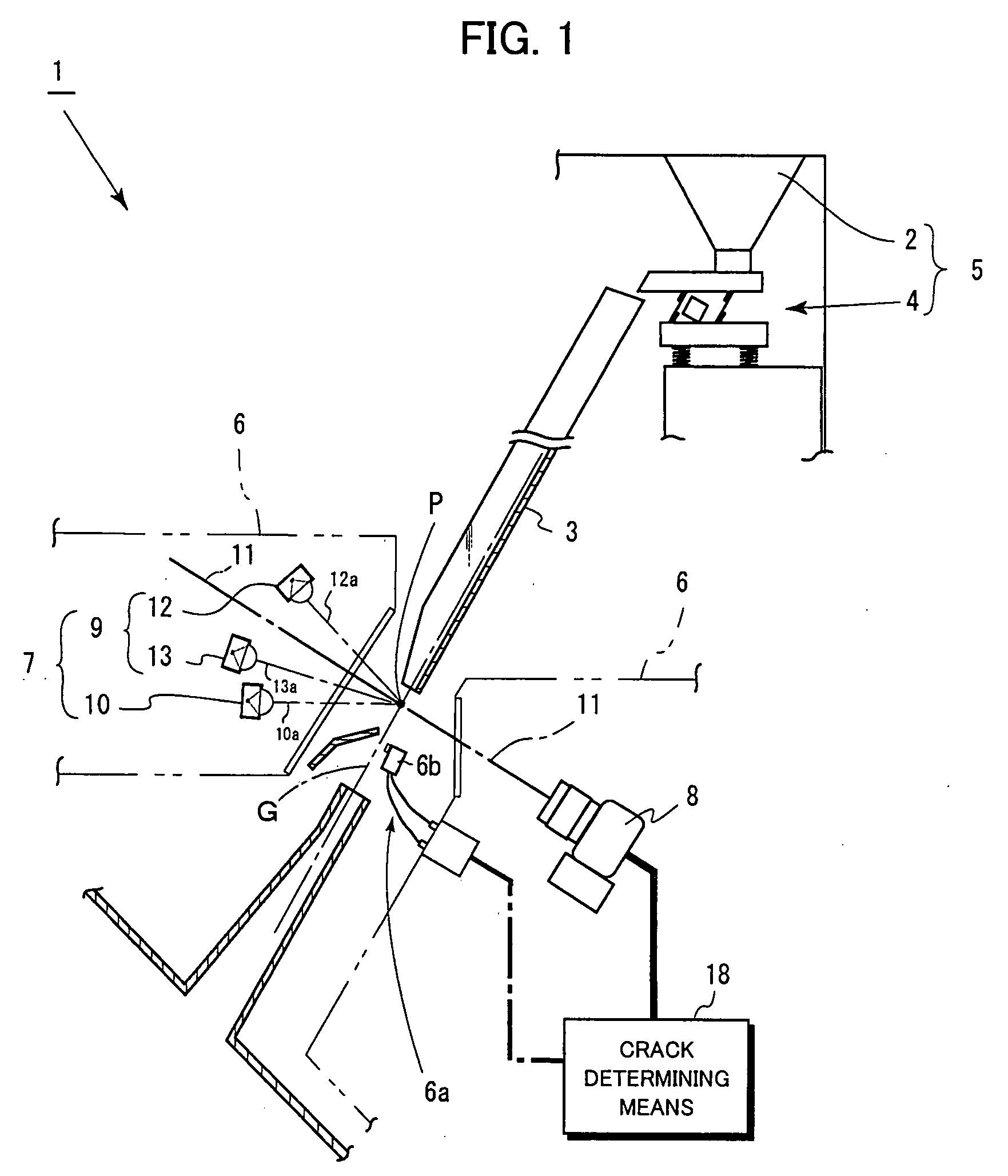
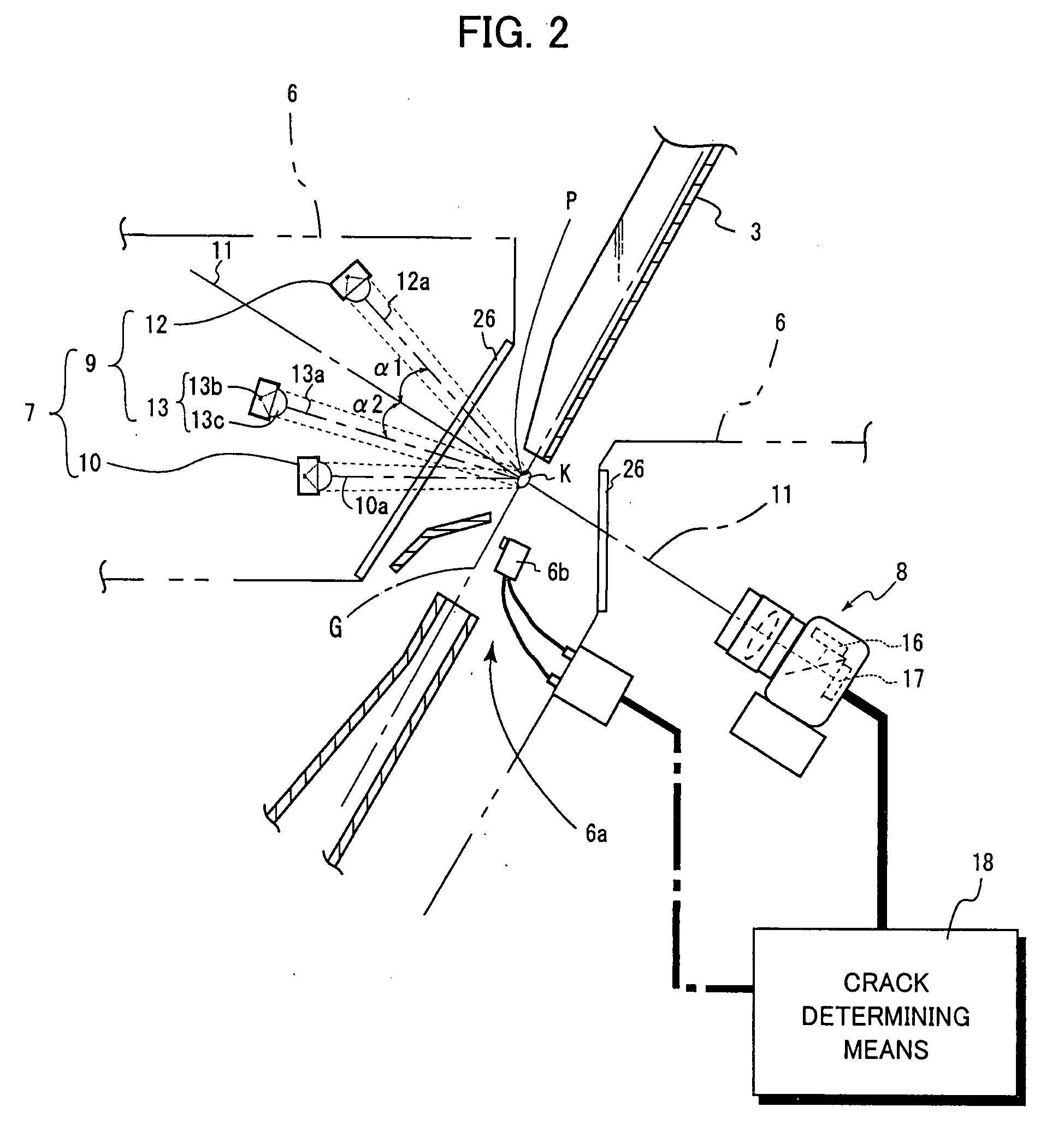
[0015]According to the optical cracked-grain selector of the present invention, the identification unit mounted on the crack determining means forms a first rice grain image showing cracks, embryo and scratches based on light passed through the rice grain and detected by the first CCD built into the CCD camera as well as a second rice grain image showing the embryo and scratches based on light passed through the rice grain and detected by the second CCD built into the CCD camera, cancels out images of the embryo and scratches by calculating the difference in the amount of light between these two images and acquires (identifies) a crack image showing only cracks, and determines whether or not the rice grain is a cracked grain based on the crack image. As a result, when identifying cracked grains, there are no more misidentifications of normal grains having no cracks as cracked grains due to the effect of images of the embryo and scratches, and accordingly, cracked grains can be correctly selected for removal, thus improving product yield.

Problems solved by technology

However, each grain of rice has an embryonic portion and sometimes also surface cracks in the skin (hereinafter “scratches”), and it is known that the embryonic portions and the scratches adversely affect identification accuracy when identifying cracked grains.
In other words, when the embryonic portion and scratches are present in the rice grain, they show up as dark shadows just like cracks, and for that reason normal grains having no cracks are wrongly identified as cracked grains, causing a decline in product yield.

Method used


Image

  • Optical cracked-grain selector
  • Optical cracked-grain selector
  • Optical cracked-grain selector

Examples


Embodiment Construction

[0026]A detailed description will now be given of a preferred embodiment of the present invention, with reference to the drawings.

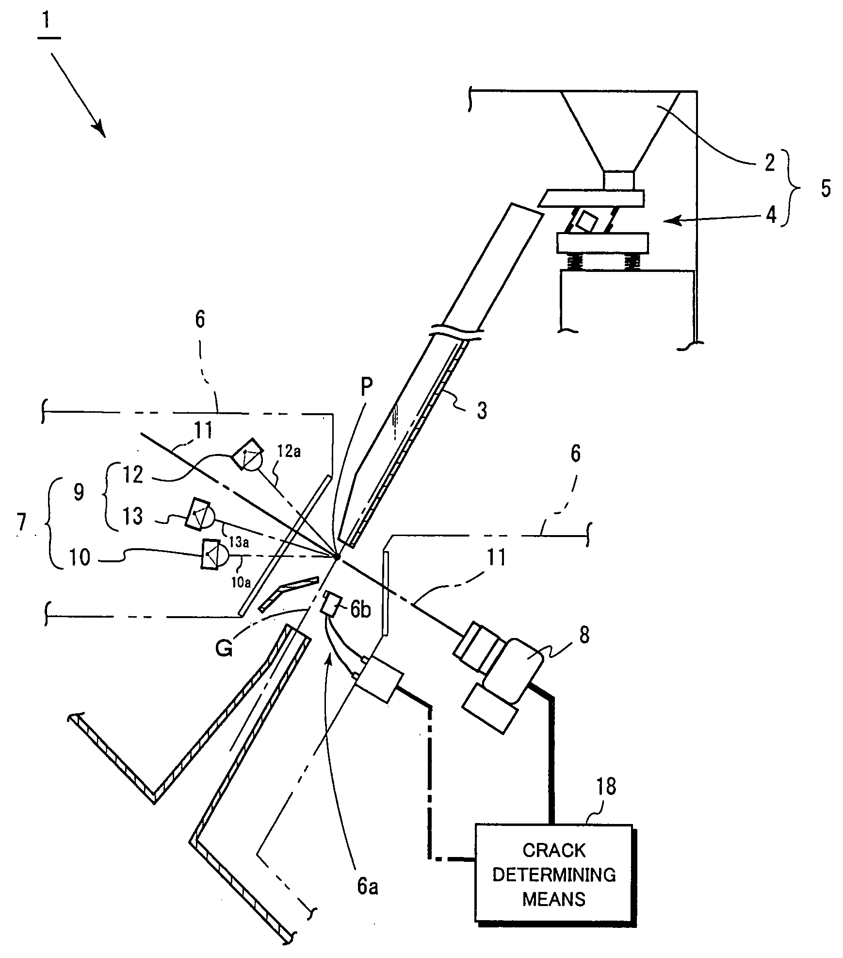
[0027]FIG. 1 is a vertical side sectional view of an optical cracked-grain selector 1 of the present invention. FIG. 2 is an enlarged view of the main parts of that optical cracked-grain selector 1. The optical cracked-grain selector 1 is composed of a raw material tank 2 that holds material rice grains K, a vibrating feeder 4 that sends in succession material rice grains expelled from the raw material tank 2 to a slanted chute 3 that is described later, and the downwardly slanting slanted chute 3. In the present embodiment, the angle of the downward slant of the slanted chute 3 is 45 degrees. A plurality of adjacent grooves in the downward direction are formed in a slanted surface of the slanted chute 3 so as to align the individual grains of raw rice K in the long direction of the rice grains and pour them downward (see FIG. 3a). In the present embodime...


PUM


Abstract

An optical cracked-grain selector that does not mistakenly identify normal grains of rice having no cracks as cracked grains due to the presence of the embryonic portion and / or surface scratches when optically identifying cracked grains of rice mixed in with material rice grains. An identification part in a cracked grain identification unit obtains a first rice grain image (having an embryonic portion and scratches) based on light passed through the rice grain that is received by a first CCD sensor built into a CCD camera of a photoreaction detection unit and a second rice grain image (having cracks, an embryo portion and scratches) based on light passed through the rice grain received by a second CCD sensor built into the CCD camera, acquires an image of the cracks by calculating a difference in the amount of light between the two rice grain images, and identifies a cracked grain.

Description

BACKGROUND OF THE INVENTION[0001]1. Field of the Invention[0002]The present invention relates to an optical cracked-grain selector that optically determines and selects for removal cracked grains in material rice grains such as brown rice, polished rice and the like.[0003]2. Description of Related Art[0004]Conventionally, an optical cracked-grain selector apparatus that optically detects and selects grains of rice having one or more cracks that penetrate to the interior of the grain (hereinafter “cracked grain” or “cracked grains”) is known, such as those disclosed in JP2005-265519A and JP3642172B. In general, the above-mentioned crack in the rice grain usually extends in a direction substantially perpendicular to a longitudinal direction of the rice grain. As shown for example in FIG. 10, a conventional optical cracked-grain selector 100 comprises a slanted chute 200 for pouring the material rice grains downward, and optical detecting means 300 and selection means 400 disposed near...

Claims


Application Information

Patent Timeline
IPC IPC(8): B07C5/342B07C5/00
CPCB07C5/366B07C5/3425
Inventor ITO, TAKAFUMIHARA, MASAZUMIEGI, MASAHIRODOI, TAKAHIRO
Owner SATAKE CORP
Learn More