
Liquid Dispensing Valve

a liquid dispenser and valve body technology, applied in the field of liquid dispensers, can solve the problems of increasing consequently the end product to which it is coupled, and achieve the effects of eliminating or eliminating or reducing the cost of the valv

Inactive Publication Date: 2007-11-15
WHIRPOOL SA
View PDF11 Cites 2 Cited by
  • Summary
  • Abstract
  • Description
  • Claims
  • Application Information

AI Technical Summary

Benefits of technology

[0009] As a function of the operational disadvantage mentioned above, it is an object of the present invention to provide a liquid dispensing valve to be operatively associated with a reservoir to be mounted inside a refrigeration appliance, said dispensing valve presenting a simple and strong construction of low cost, which eliminates or at least considerably minimizes the dripping of the residual liquid still contained inside the valve body after the closing of the latter by the collecting recipient being removed from below the elongated spout of said dispensing valve.
[0010] It is a further object of the present invention to provide a liquid dispensing valve such as defined above, which minimizes the cooling of the valve body and consequently the condensation of the ambient humidity around the latter by the liquid maintained under refrigeration inside the reservoir.
[0011] It is another object of the present invention to provide a liquid dispensing valve such as defined above, which can be moved jointly with the reservoir to which it is coupled during the mounting and dismounting operations of the latter in relation to the structure of the refrigeration appliance to which it is coupled, facilitating the cleaning operations of said reservoir.
[0012] It is an additional object of the present invention to provide a liquid dispensing valve such as defined above, which can be easily mounted and dismounted in relation to the lower discharge nozzle of the reservoir.

Problems solved by technology

However, in these constructions the amount of residual water contained inside both the valve body and the elongated spout, which are disposed downstream the valve seat, flows down gravitationally, until said volume of residual liquid is completely depleted from the interior of both the body and the elongated spout.
While it is possible to construct liquid dispensing valves presenting means which at least minimize the dripping of the residual liquid still contained inside the body of the dispensing valve after the closing of the latter, such constructions tend to considerably increase the cost of the valve and consequently of the end product to which it is coupled.

Method used


Image

  • Liquid Dispensing Valve
  • Liquid Dispensing Valve
  • Liquid Dispensing Valve

Examples


Embodiment Construction

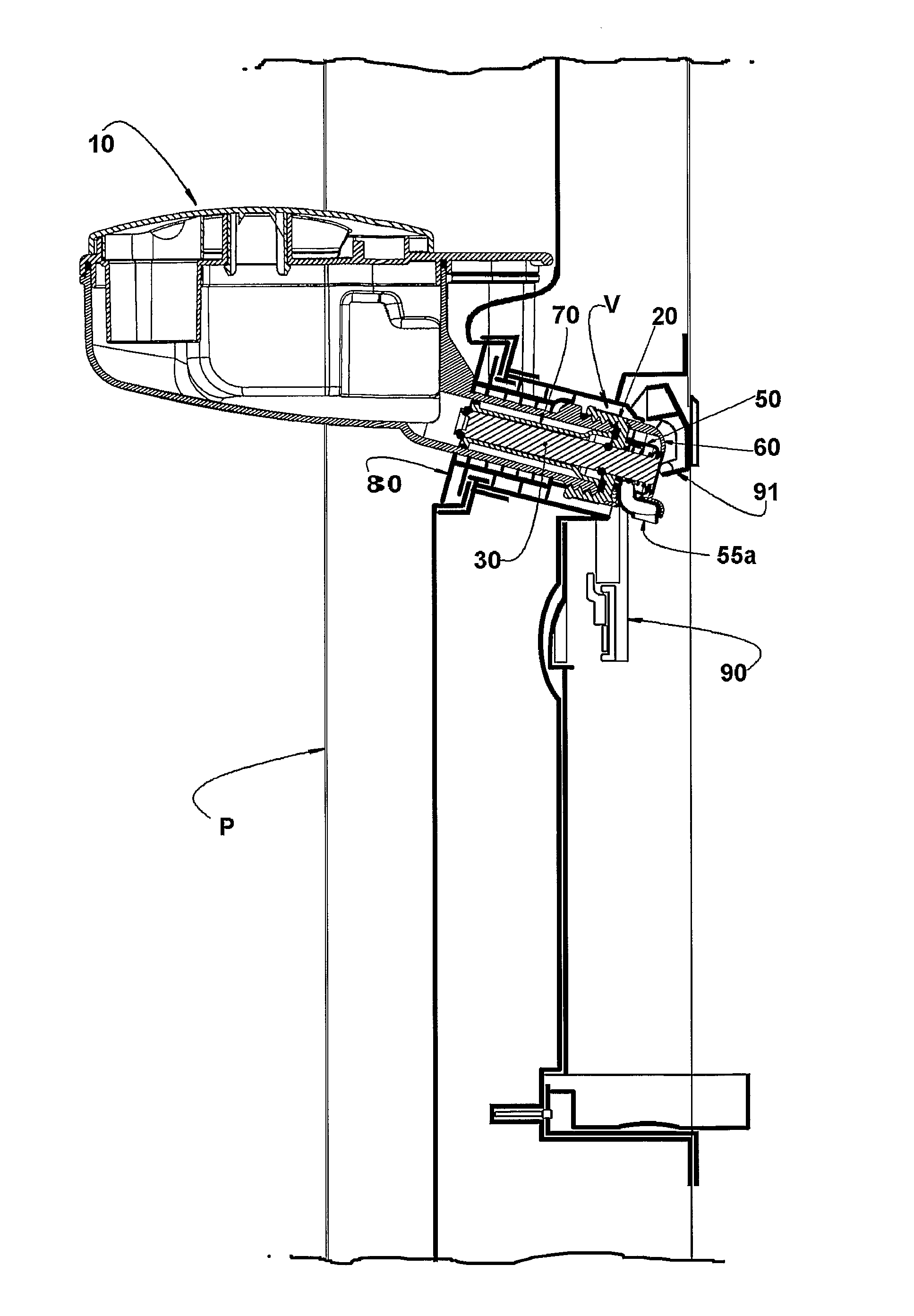
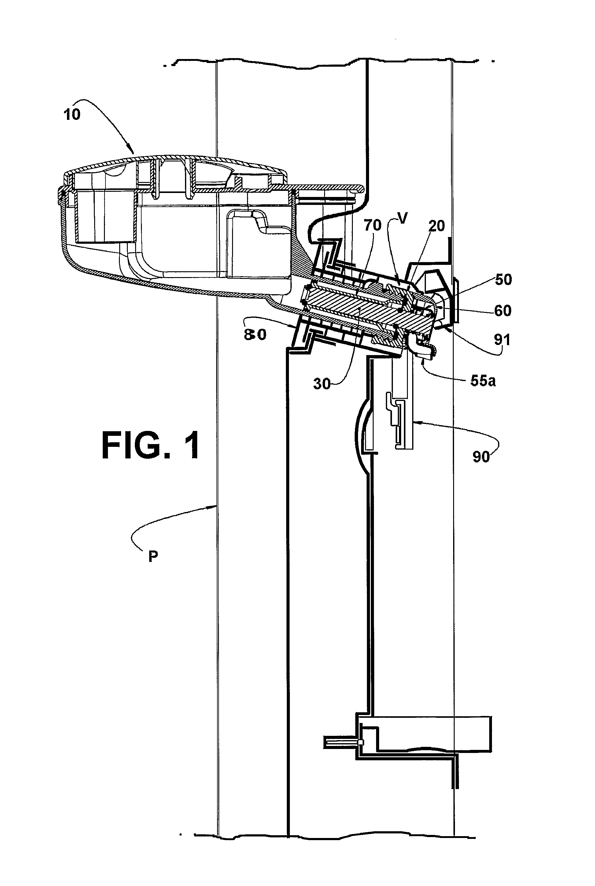
[0019] As previously mentioned and in accordance with the enclosed drawings, the present liquid dispensing valve is applied to a reservoir 10 to be mounted inside a refrigeration appliance, more exactly inside a refrigerating compartment, so as to keep refrigerated the liquid stored in said reservoir. Although it is possible to configure the reservoir 10 in different manners and to mount it in different places inside the refrigerating compartment, it is usually preferred to apply it to the internal panel of the door “P” of said refrigerating compartment, and provided it with an elongated lower discharge nozzle 11 disposed through the thickness of the front door “P” of the refrigerating compartment so as to allow the user to help himself / herself of the liquid stored in the reservoir from the outside of the door “P” with no need of opening the latter.

[0020] In the illustrated embodiment, the reservoir 10 takes the form of the one described and claimed in Brazilian Patent Application ...


PUM


Abstract

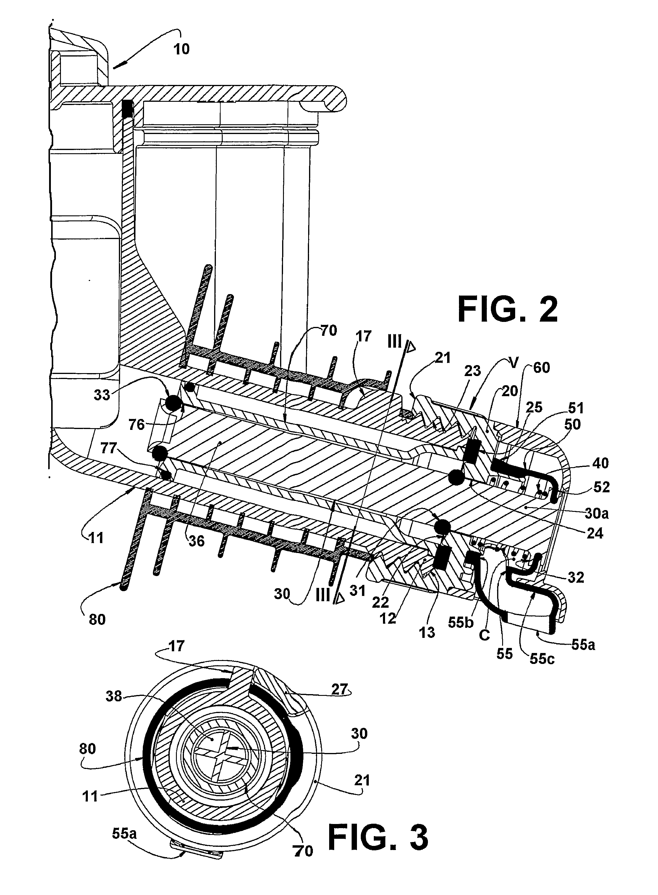
A liquid dispensing valve comprising: a body portion (20) hermetically mounted to a free end (12) of a discharge nozzle (11) of a reservoir (10) and defining a seat (22); a rod (30) carrying a seal (31) and being selectively displaced between a closing position in which the seal (31) is seated on the seat (22), and a maximum opening position in which the seal (31) is spaced from the seat (22); a cap portion (50) hermetically affixed to the body portion (20) downstream the seat (22) and around the rod (30), and defining a discharge chamber (C); and an elongated spout (55) having a discharge end (55a) turned downwards, said cap portion (50) and elongated spout (55) being configured and dimensioned so that, when the seat (22) is closed, the mass of residual liquid contained in the discharge chamber (C) forms, inside the latter, a vacuum which is sufficient to retain said mass of liquid inside the dispensing valve (V).

Description

FIELD OF THE INVENTION [0001] The present invention refers to a liquid dispensing valve to be operatively associated with a reservoir, such as reservoir for water or other liquids, provided inside a refrigerator and which allows the user to control the selective and gravitational release of the liquid into any recipient, such as a glass, a mug, et c. PRIOR ART [0002] There are well known from the art different constructions for a water reservoir to be mounted close to the internal panel of the front door of a refrigerating compartment of a refrigeration appliance defined by a refrigerator or a combined freezer-refrigerator appliance. A construction of this type is described in Brazilian Patent Application PI0302286-2 filed on Jun. 1st, 2003 by the same applicant. [0003] In the type of assembly mentioned above, as well as in other applications in which the liquid is gravitationally dispensed from the reservoir, the latter is provided with a lower discharge nozzle to which is directly...

Claims


Application Information

Patent Timeline
IPC IPC(8): B67D3/00B67D1/00B67D1/12B67D3/04F25D23/12
CPCB67D1/1256F25D23/126B67D2210/00036B67D3/043B67D3/04B67D1/12
Inventor AMARAL, CLAITON EMILIO DOBENTO, EDSON ISALTINO
Owner WHIRPOOL SA
Learn More