Device and process for mounting a rotor of a hermetic compressor

a technology of rotor and compressor, which is applied in the direction of positive displacement liquid engine, magnetic circuit rotating parts, magnetic circuit shape/form/construction, etc., can solve the problems of insufficient strength to withstand, impair the reliability of the compressor to be produced, and the possibility of misalignment, so as to achieve the effect of minimizing the risk of misalignment and easy and safe operation

Inactive Publication Date: 2005-01-18
EMPRESA BRASILEIRA DE COMPRESSORES SA (EMBRACO)
View PDF5 Cites 2 Cited by
  • Summary
  • Abstract
  • Description
  • Claims
  • Application Information

AI Technical Summary

Benefits of technology

It is a further object of the present invention to provide a mounting process by mechanical interference, which is easily and safely achieved, in order to guarantee the fixation, by mechanical interference, of the rotor of an electric motor to the crankshaft of a hermetic compressor, without requiring preheating or unnecessary efforts over the structure of the rotor and minimizing the risks of occurring misalignments between the parts during the mounting operation.

Problems solved by technology

However, in other rotors, such as for example, those in which the magnets are affixed to the rotor core only by gluing, dispensing the use of the external steel cover, the resulting structure, although being simpler, less expensive, and electromagnetically more efficient, is not strong enough to withstand, with no risks of damages, the efforts and the temperature to which it is submitted if mounted by interference with previous heating.
The heating to be applied to the rotor, so that it may be mounted around the crankshaft, jeopardizes the gluing of the magnets around the rotor core or other structural characteristics, impairing the reliability of the compressor to be produced.
This possibility of misalignment is mainly due to the fact that the axial force applied to the crankshaft is compressive, acting against the end of the crankshaft opposite to the rotor.
The mounting misalignments, even being small, tend to provoke unacceptable deformations in the assembly to be formed.
The mounting solutions, which have been proposed to such rotors of fragile construction, require complex procedures that will increase the cost of the final product, as it occurs, for example, when the fixation of the rotor to the crankshaft is made by gluing.

Method used


Image

  • Device and process for mounting a rotor of a hermetic compressor
  • Device and process for mounting a rotor of a hermetic compressor
  • Device and process for mounting a rotor of a hermetic compressor

Examples


Embodiment Construction

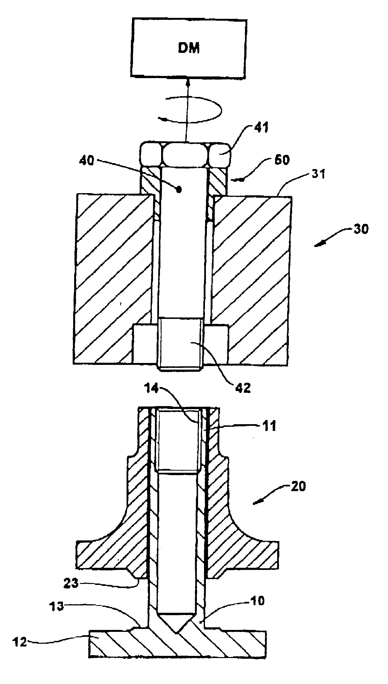
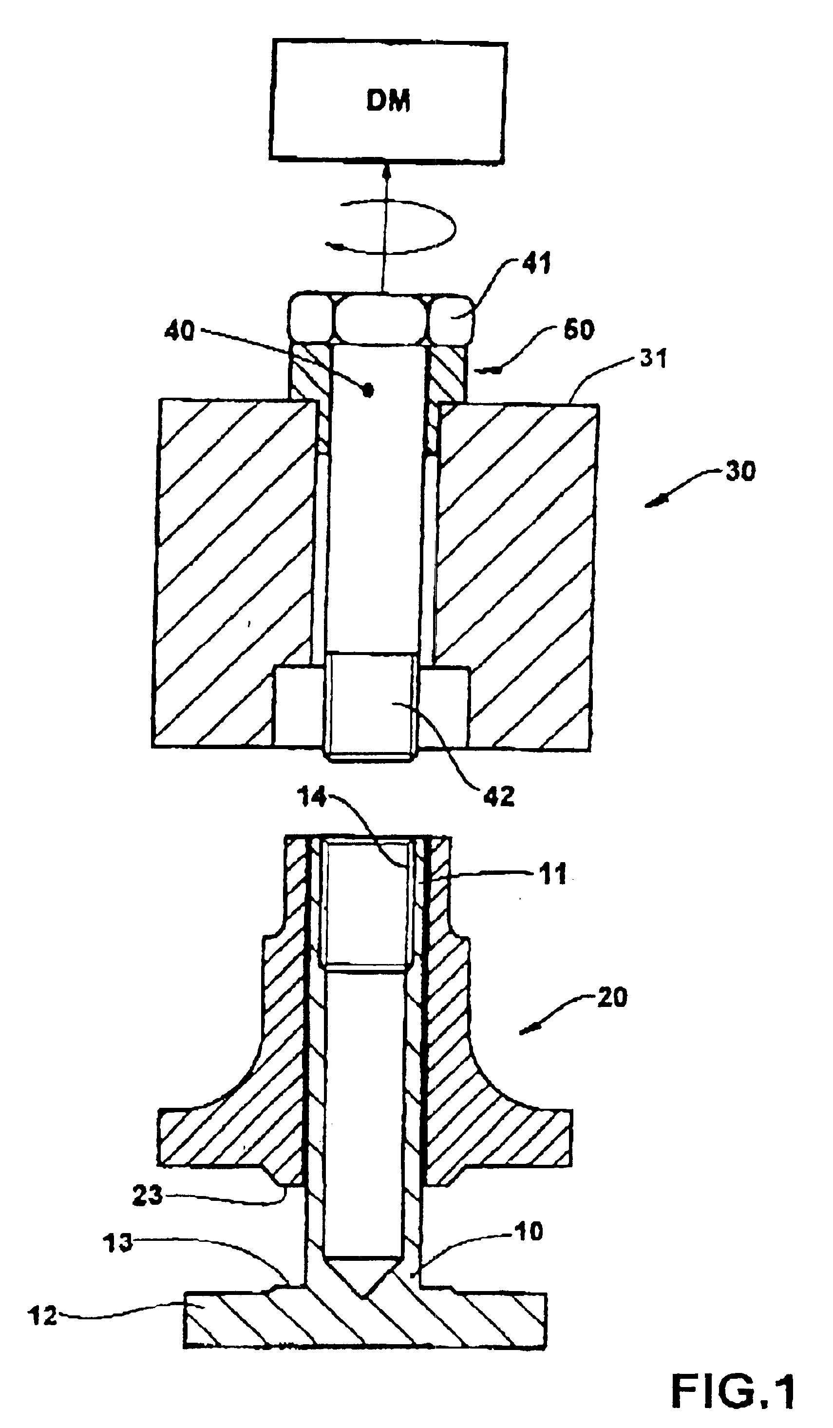
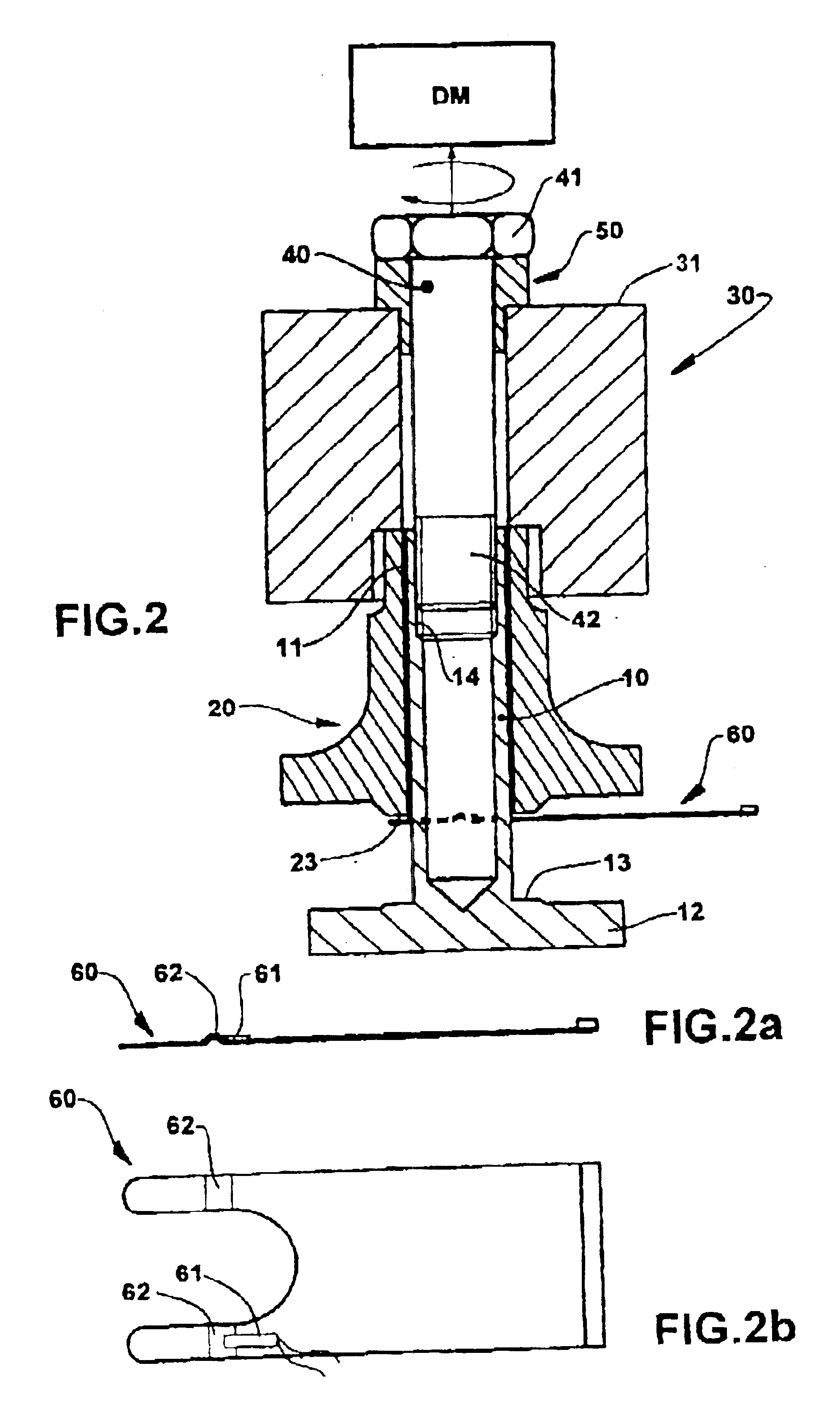
As illustrated in the drawings, the present mounting device and process are applied to a hermetic compressor, whose crankshaft 10, which is journalled through a bearing hub 20, has an extension 11, around which is affixed a rotor 30 of the electric motor of the compressor, and which incorporates an end flange 12 defining an annular surface 13 to be axially seated against a respective end annular face 23 of the bearing hub 20.

According to the illustrated embodiment, the mounting device of the present invention comprises a pulling rod 40, usually in the form of a screw having a diameter that is substantially smaller than the internal diameter of the rotor and having a length, which is larger than the axial extension of the rotor 30. The pulling rod 40 incorporates, at an end thereof, an enlarged head 41, which is preferably configured to receive a driving means, generally a tool for applying a rotary movement (not illustrated), said enlarged head 41 being dimensioned to be seated agai...


PUM

PropertyMeasurementUnit
axial displacementaaaaaaaaaa
axial mounting displacementaaaaaaaaaa
thicknessaaaaaaaaaa

Abstract

A device and a process for mounting the rotor of a hermetic compressor, said device comprising a pulling rod (40), which is loosely and coaxially provided through the rotor (30) of the electric motor of the compressor, in order to have a first end coupled to an end of the crankshaft (10) located adjacent to an end face of the rotor (30), and a second opposite end to be seated against an opposite end face of the rotor (30) and to which a driving means (DM) is engaged to move the pulling rod (40), in order to provoke a relative axial displacement of the crankshaft (10), sufficient to fit, by mechanical interference, the extension (11) of the crankshaft (10) inside the rotor (30).

Description

FIELD OF THE INVENTIONThe present invention refers to a device and a process for providing the mounting and fixation of the rotor of an electric motor to the crankshaft of a hermetic compressor of the type normally used in small refrigeration systems.BACKGROUND OF THE INVENTIONOne of the known constructions to obtain the fixation of the rotor of an electric motor to the crankshaft of the compressor uses mounting by mechanical interference. In this prior art arrangement, the rotor is heated to a certain temperature, which is insufficient to damage its structure, but which promotes a thermal dilatation that is necessary to allow the introduction of the crankshaft inside the rotor, without requiring mechanical efforts that may impair the structure of the rotor. After introducing the crankshaft into the rotor, the latter, already under a cooling process, exerts pressure around the crankshaft by thermal contraction, guaranteeing the rotational and axial locking between the rotor and the ...

Claims


Application Information

Patent Timeline
Patent Type & Authority Patents(United States)
IPC IPC(8): F04B39/14H02K15/02H02K1/28H02K1/30H02K7/14F04B39/00H02K7/00
CPCF04B39/14H02K1/30H02K7/14H02K15/028Y10T29/4924Y10T29/49012Y10T29/53143Y10T29/49865Y10T29/49238Y10T29/49009
Inventor LILIE, DIETMAR ERICH BERNHARDODORCZYK, MARCOS FERNANDO
Owner EMPRESA BRASILEIRA DE COMPRESSORES SA (EMBRACO)
Why Eureka
Try Eureka