Mounting plate for lock and lock therewith

a technology for mounting plates and locks, applied in the direction of fastening devices, construction, fastening means, etc., can solve the problems of electromagnetically falling and hurting workers working there below, and achieve the effect of convenient installation

Inactive Publication Date: 2007-11-15
HWANG SHIH MING
View PDF5 Cites 676 Cited by
  • Summary
  • Abstract
  • Description
  • Claims
  • Application Information

AI Technical Summary

Benefits of technology

[0014] It is an object of the present invention to provide a mounting plate for electromagnetic locks that overcome inadequacies including the possibility of the electromagnetic lock being displaced prior to fixing the lock in a permanent position, the difficulty of precisely mounting the electromagnetic lock into that permanent position, and the possibility of the electromagnetic lock of falling and accidentally hurting someone below the lock, including even the installer.
[0015] It is another object of the present invention to provide a mounting plate for a lock having the advantages of being easy in install and very safe.
[0016] To achieve the above and other advantages, the present invention provides a mounting plate mounted on a top of the electromagnetic body of an electromagnetic lock as way of fixed the electromagnetic body being on a door post. The mounting plate comprises a plurality of mounting apertures at both ends and a plurality of mounting holes in between the mounting apertures, the mounting holes being elliptical in shape and spaced apart by a predetermined distance, and each of the mounting apertures comprising an inner flange formed along an edge thereof wherein the flange of one of the mounting holes is placed opposite the flange of any adjacent mounting holes, By utilizing this mounting plate, the electromagnetic body will be prevented from disengaging from the mounting plate to which is to be fastened should it be accidentally or purposely turned. Otherwise, the electromagnetic body may accidentally fall and hurt a worker working there below. With this design, the edge of each mounting screw head is adapted to obliquely insert into the mounting hole and then slide clockwise to rest on the flange, and finally a plurality of screws are driven through the mounting plate for securing the mounting plate onto the electromagnetic body.

Problems solved by technology

Otherwise, the electromagnetic body may accidentally fall and hurt a worker working there below.

Method used


Image

  • Mounting plate for lock and lock therewith
  • Mounting plate for lock and lock therewith
  • Mounting plate for lock and lock therewith

Examples


Embodiment Construction

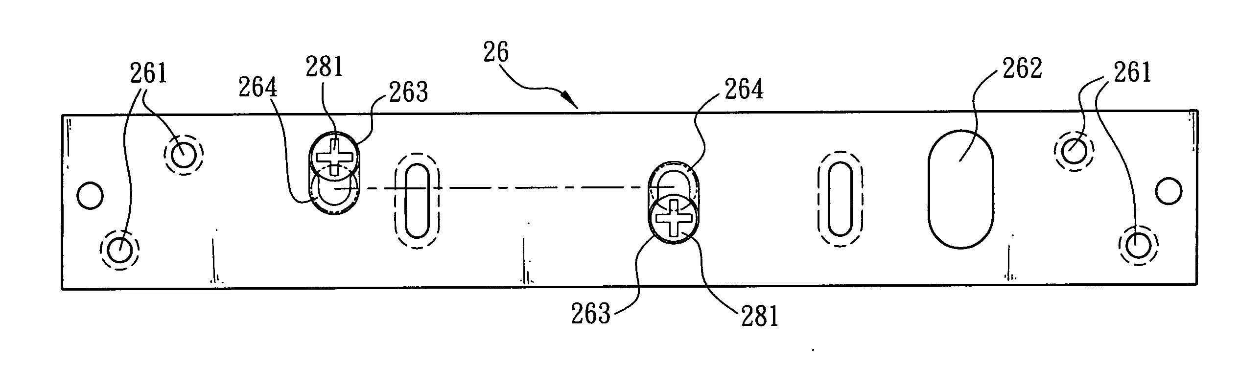
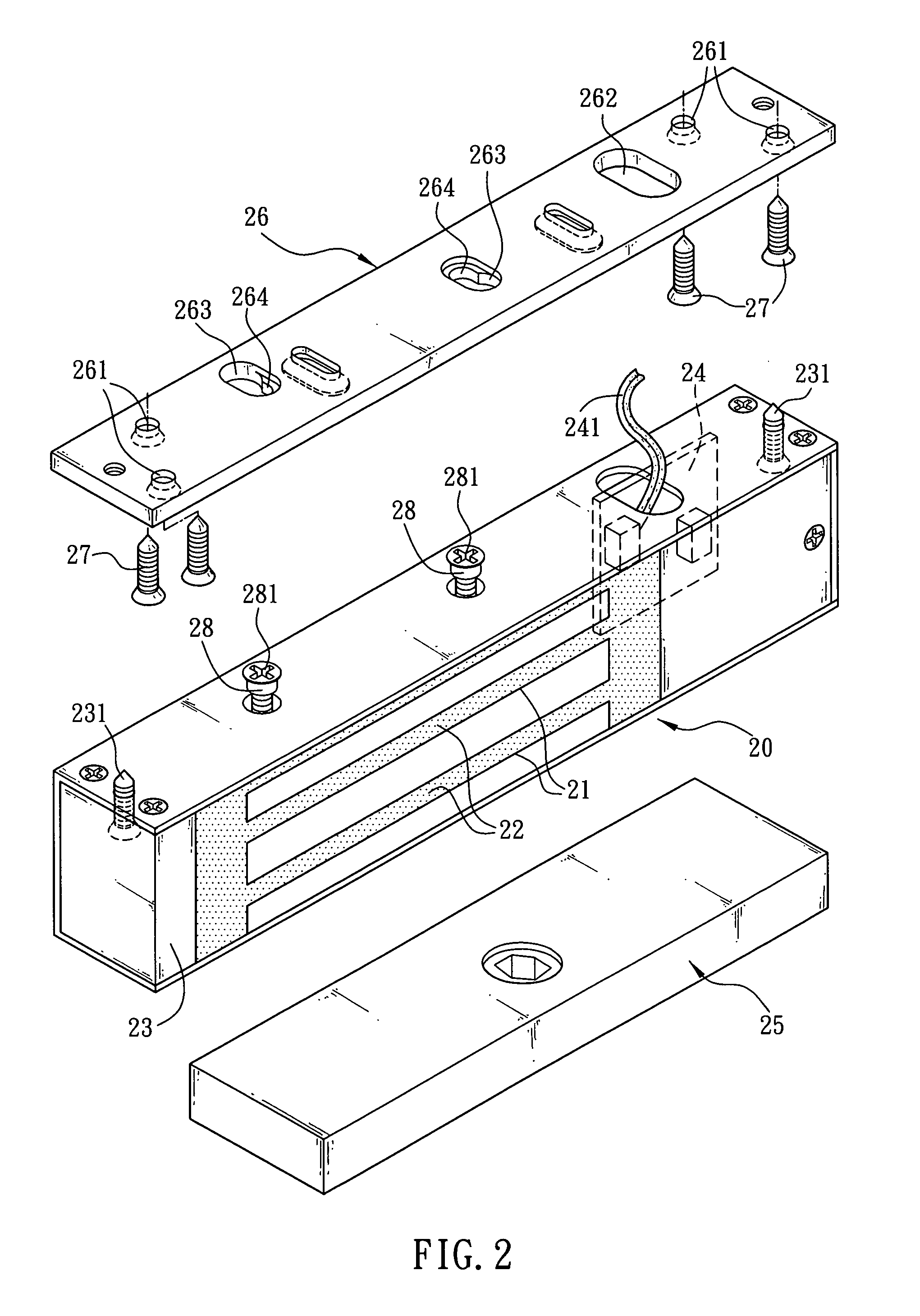
[0023] Referring to FIG. 2 and FIG. 3, a mounting plate for electromagnetic locks that facilitates the mounting of an electromagnetic lock on a fixed door frame or door post with a plurality of mounting holes designed to overcome safety issues with a preferred embodiment of the invention is shown. In the preferred embodiment the lock comprises two bodies in which one body is a electromagnetic body 20 and the other one is a metal block 25. When installed, the electromagnetic body 20 is mounted on a fixed door frame or door post 30 and the metal armature plate 25 is mounted on a pivotal or sliding door or gate 40. The metal armature plate 25 is secured to the door frame or gate post 30 in such a position that the metal armature plate 25 and the electromagnetic body 20 can touch each other the door or gate is closed.

[0024] The electromagnetic body 20 typically comprises a plurality of transverse grooves 21 and an electromagnet 22 formed by winding a coil of wire around the grooves of ...


PUM


Abstract

The present invention relates to a mounting plate for a lock and a electromagnetic lock therewith, wherein a top of a lock body (e.g., a electromagnetic body) of a lock is fixed on a door frame via a mounting plate, the mounting plate comprising a plurality of mounting apertures placed at both ends thereof, and a plurality of mounting holes which an elliptical shape being spaced apart by a predetermined distance, and being provided in a portion between the mounting apertures, and each of the mounting apertures comprising an inner flange formed along an edge thereof wherein the flange of one of the mounting holes is placed opposite the flange of any adjacent one of the mounting holes. In installation, edge of head of each mounting screw on top of lock body is adapted to obliquely insert into the mounting holes and then slide clockwise to rest on the flange. Finally, a plurality of screws are driven through the mounting plate for securing the mounting plate onto the electromagnetic body.

Description

BACKGROUND OF THE INVENTION [0001] 1. Field of the Invention [0002] The present invention relates to mounting plates for electromagnetic locks and more particularly to a mounting plate that facilitates the mounting of an electromagnetic lock on a fixed door frame or door post with a plurality of mounting holes designed to overcome safety issues related to the possibility of the electromagnetic lock falling and accidentally hurting a worker during installation. [0003] 2. Description of the Prior Art [0004] The technology employed in the design and building of electromagnetic locks has developed rapidly in the past few decades, resulting in a significant improvement in the quality of such locks. A wide variety of electromagnetic locks are produced by several manufacturers of the art. Such electromagnetic locks are now mass-produced, and are characterized by being structurally strong, durable, power saving, and causing no pollution to the environment. However, little has been done in t...

Claims


Application Information

Patent Timeline
Patent Type & Authority Applications(United States)
IPC IPC(8): E05C19/16
CPCE05C19/166Y10T292/11
Inventor HWANG, SHIH-MINGHWANG, LIANG-LUNHWANG, CHIEN-JONG
Owner HWANG SHIH MING
Why Eureka
Try Eureka