Mechanic's seat and step stool

a technology of seat and seat frame, applied in the field of molded work seats, can solve the problems of not being able to move the chair the use of the chair may not be convenient or adequate, and the chair is difficult to move from one place to another, and the storage typically will not include a means of storag

Inactive Publication Date: 2007-11-15
LISLE CORPORATION
View PDF2 Cites 12 Cited by
  • Summary
  • Abstract
  • Description
  • Claims
  • Application Information

AI Technical Summary

Benefits of technology

[0007] Briefly, the present invention comprises a molded polymeric, step stool and seat which is in the form of a six-sided, rectangular parallelepiped and includes a first wall having casters and a second opposite side wall with a molded work seat. A third transverse sidewall connecting the top edge of the first and second walls defines a flat planar step surface. A fourth transverse wall is generally parallel to and spaced from the third wall and connects the lower edge of the first and second walls defines a floor support surface including optional floor support pads to prevent skidding of the device when it serves as a step stool. The fourth wall may also include a recess shelf for storage of tools and implements. In an additional embodiment, the first wall may include a molded step below the level of the third wall to facilitate stepping to the third wall step surface.
[0009] It is a further object of the present invention to provide a molded polymeric combination step stool and creeper seat which is lightweight, economical, and rugged.
[0011] Yet another object of the invention is to provide a mechanic's creeper seat which may be mounted on casters for ease of mobility.

Problems solved by technology

When a worker, such as a mechanic, tradesman, or the like is required to assume a seated position in order to perform repair work, the use of a chair may not be convenient or adequate.
Additionally, such a chair is difficult to move from one place to another.
Finally, such a chair typically will not include a means for storage of tools for easy access while using the chair or seat.
A stool will typically have many of the disadvantages associated with a chair including the further disadvantage that there is no lateral or back support when sitting on a stool.
Such chairs, seats and stools are either cumbersome or have other disadvantages as discussed above.

Method used


Image

  • Mechanic's seat and step stool
  • Mechanic's seat and step stool
  • Mechanic's seat and step stool

Examples


Embodiment Construction

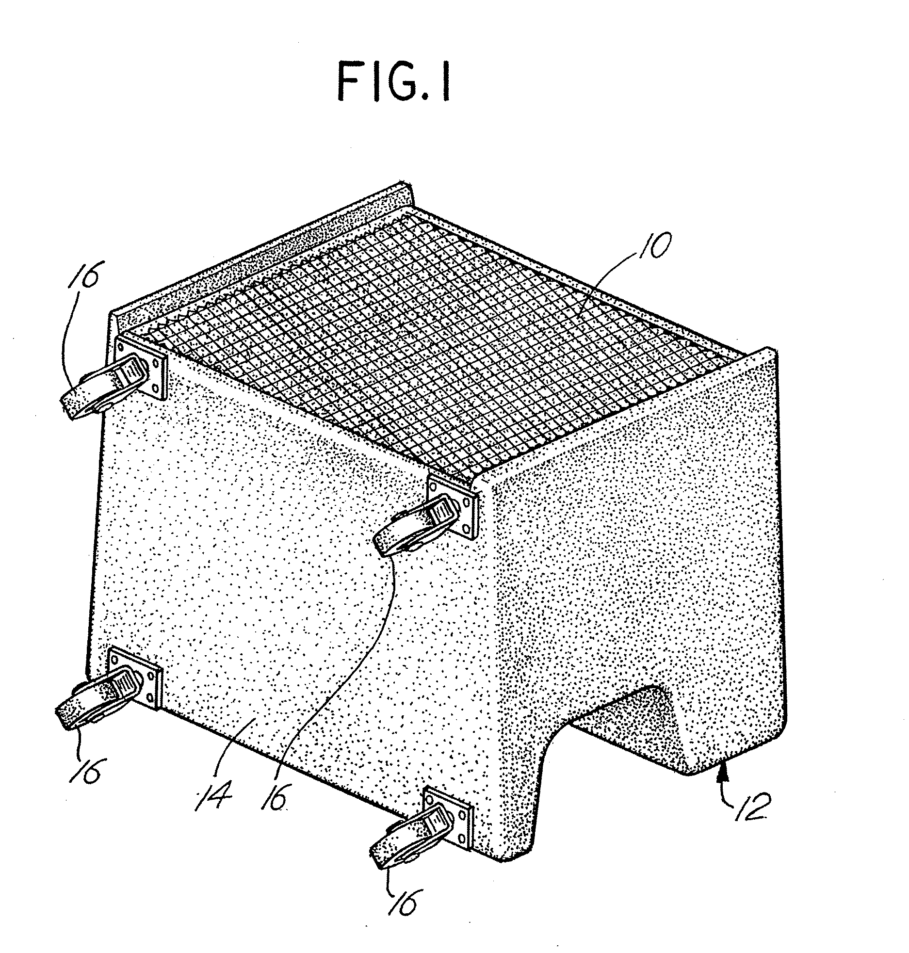
[0038]FIG. 1 illustrates a combination mechanic's seat or stool and step stool. The combination is preferably manufactured from a plastic material such as polypropylene formed by blow molding, a rotational mold process, injection molding, or other molding process. The overall general configuration is that of a parallelepiped, in particular, a rectangular parallelepiped. The molded device may have inclined sides formed with draft angles to facilitate the molding process as well as to improve the aesthetics, balance and utility of the product.

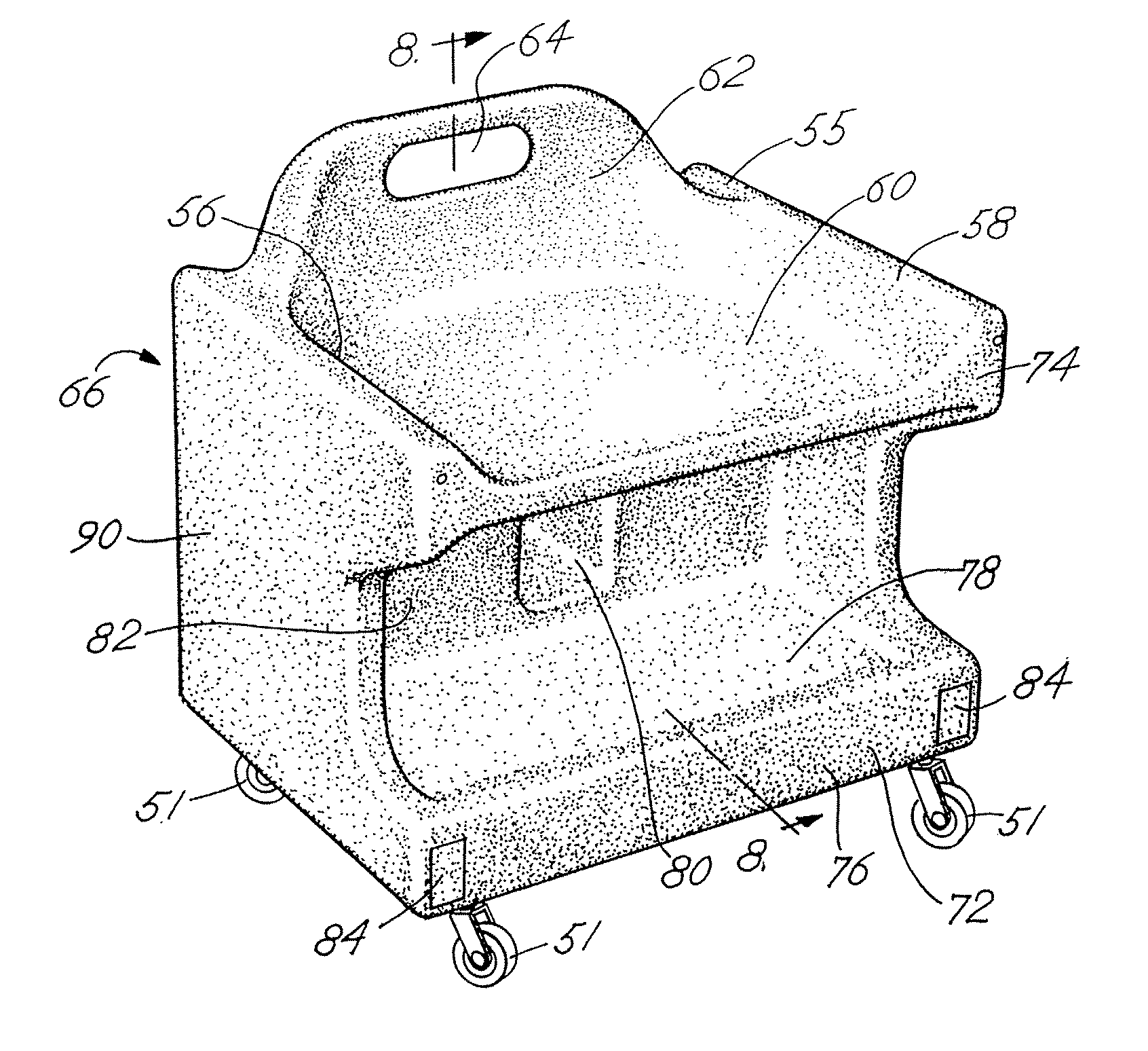
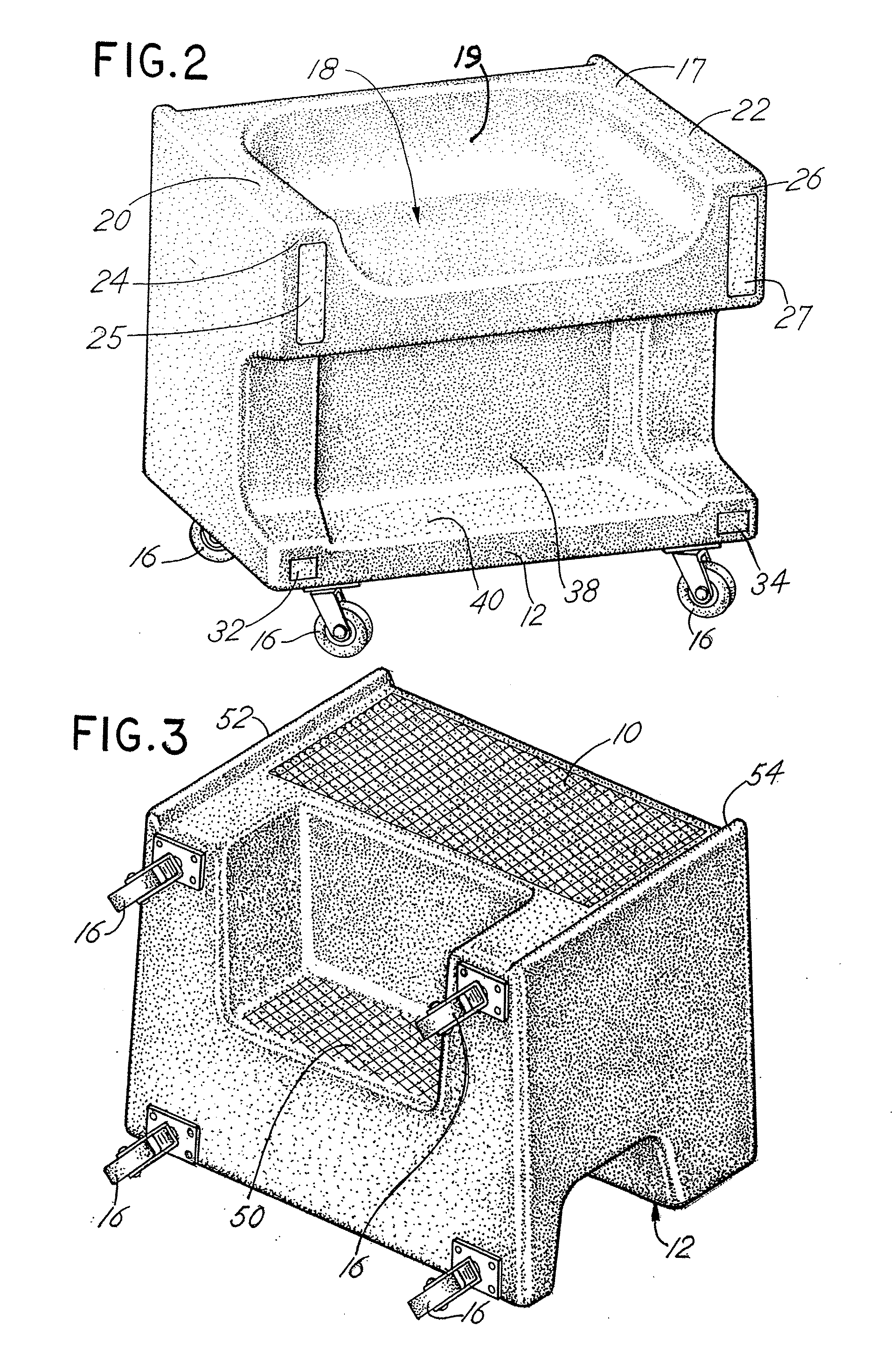
[0039] Referring to FIG. 1, the device is depicted to function as a step stool. FIG. 2 illustrates the device oriented to function as a creeper or mechanic's seat mounted on rollers or casters. When the item is utilized as a step stool, as in FIG. 1, a top face 10 includes a serrated or patterned surface to prevent slippage. A non-skid pad (not shown) may also be affixed to surface 10. Thus, top surface 10 is a generally flat, planar surface gen...


PUM


Abstract

A combination step stool and mechanic's seat in the form of a molded plastic, generally parallelepiped configuration includes a seat on one side supported on casters on the opposite side with a step stool surface adjacent the backside of the seat and spaced from a front side surface of the seat which includes a recess tray for tools and other items.

Description

CROSS REFERENCE TO RELATED APPLICATION [0001] This is a continuation-in-part application of Ser. No. 11 / 511,018 filed Aug. 28, 2006 entitled Mechanic's Seat and Step Stool, which is a continuation in part of Ser. No. 10 / 921,507 filed Aug. 19, 2004, now U.S. Pat. No. 7,097,241, which is a continuation-in-part application of Ser. No. 10 / 444,228 filed May 23, 2003, abandoned, entitled Mechanic's Seat and Step Stool which was a utility application based upon and derived from prior provisional application Ser. No. 60 / 383,206 filed May 24, 2002 for “Mechanic's Seat and Step Stool” each application being incorporated herewith by reference and for which priority is claimed. BACKGROUND OF THE INVENTION [0002] In a principal aspect, the present invention relates to a molded work seat which may also be utilized as a low-rise step stool. [0003] When a worker, such as a mechanic, tradesman, or the like is required to assume a seated position in order to perform repair work, the use of a chair ma...

Claims


Application Information

Patent Timeline
Patent Type & Authority Applications(United States)
IPC IPC(8): A47C9/02A47C12/02
CPCA47C12/00B25H5/00A47C12/02
Inventor TALLY, KEVIN L.LISLE, JOHN C.MEIS, WILLIAM J.
Owner LISLE CORPORATION
Why Eureka
Try Eureka