Jewelry storage cabinet

a jewelry storage and jewelry technology, applied in the field of jewelry storage cabinets, can solve the problems of difficult to separate jewelry, damage expensive and delicate jewelry materials, and the lidded jewelry boxes do not provide a means for displaying jewelry

Inactive Publication Date: 2007-11-15
CREED GARY D
View PDF21 Cites 26 Cited by
  • Summary
  • Abstract
  • Description
  • Claims
  • Application Information

AI Technical Summary

Benefits of technology

[0010] The plurality of drawers are vertically stacked within the lower chamber, one on top of the other, and each is slidably mounted to the pair of sidewalls. Each of the drawers may receive a padded layer for the safe and secure mounting of jewelry thereon. Additionally, the upper wall may be pivotally secured to an upper end of the rear wall of the housing, providing the user with selective access to the upper chamber.
[0011] These and other features of the present invention will become readily apparent upon further review of the following specification and drawings.

Problems solved by technology

Jewelry is often formed from expensive materials, such as gold and precious gemstones, and may be easily damaged, so that jewelry requires safe and secure storage.
For jewelry having chains, such as necklaces, or hooks, such as earrings, such storage boxes are inefficient in that the separate articles of jewelry can easily become entangled with one another, thus making it difficult to separate the jewelry and further potentially damaging the expensive and delicate jewelry materials.
Such lidded jewelry boxes do not provide a means for displaying the jewelry.
However, they are not effective for the safe and secure storage of the jewelry itself.
Typical jewelry boxes do not have adequate storage space for containing both the jewelry and the jewelry-related items.

Method used


Image

  • Jewelry storage cabinet
  • Jewelry storage cabinet
  • Jewelry storage cabinet

Examples


Embodiment Construction

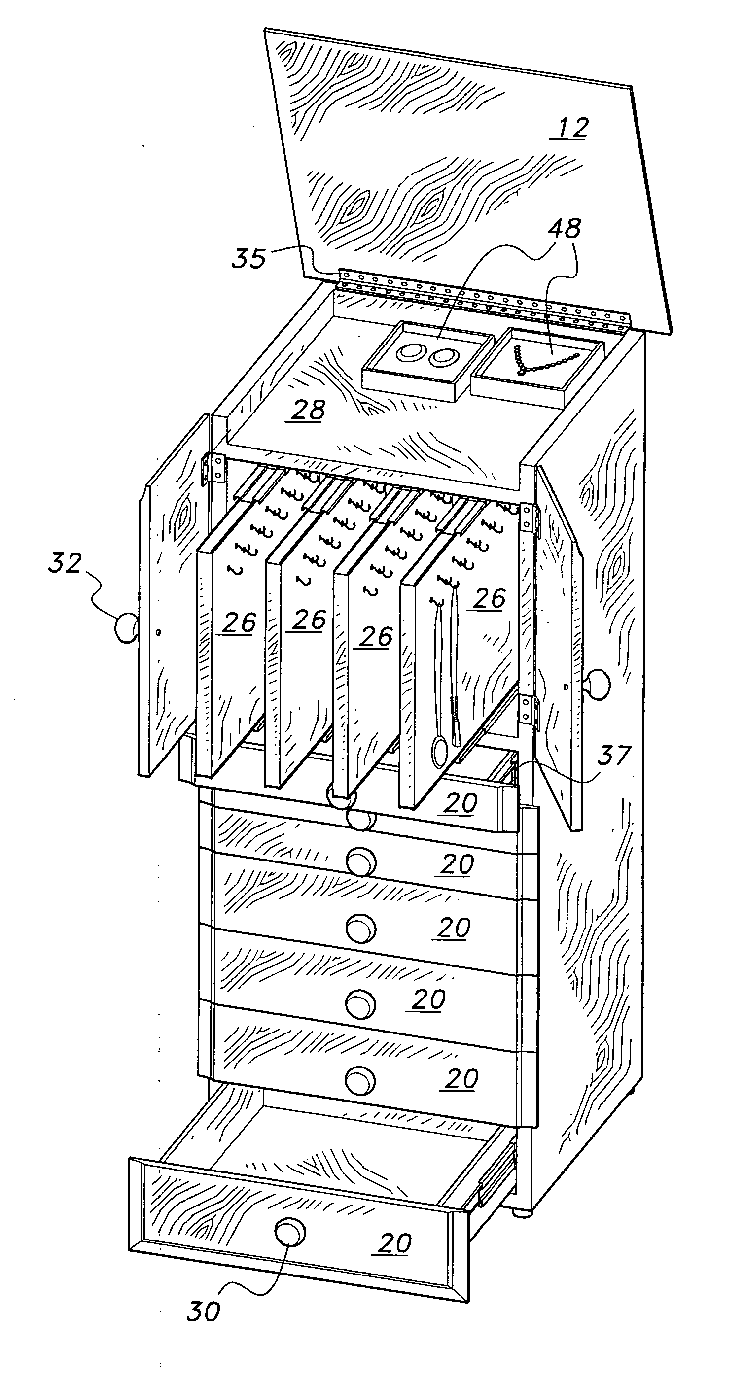
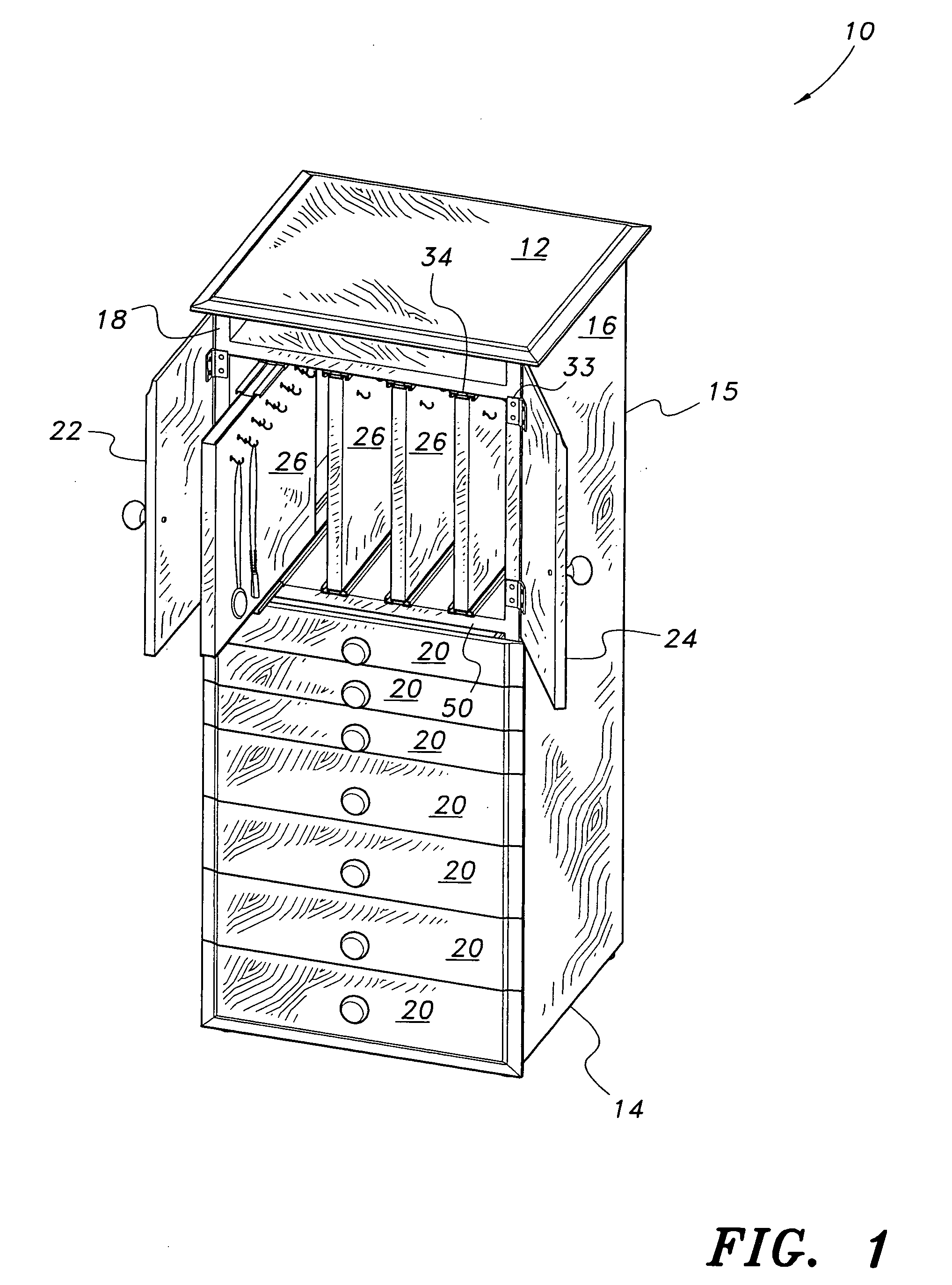
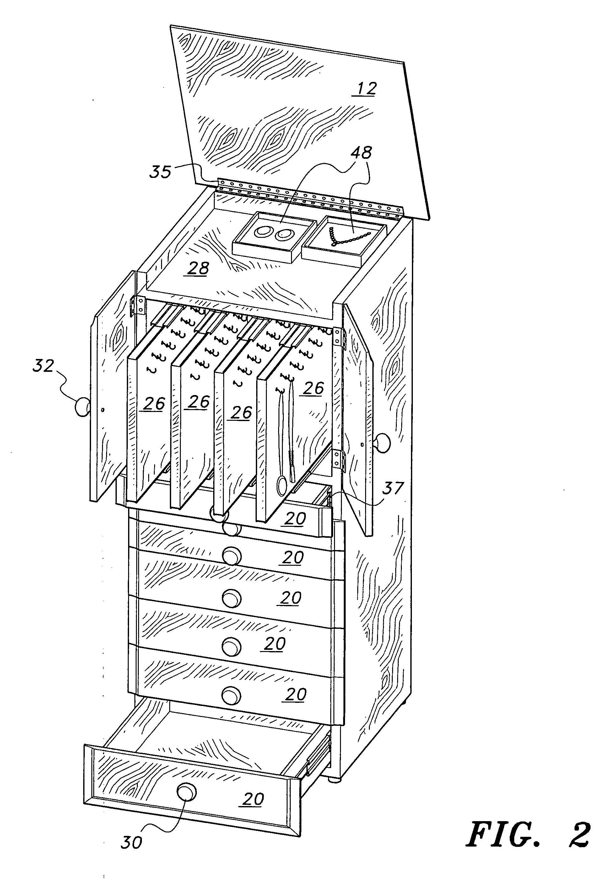
[0016] The present invention is directed towards a jewelry storage cabinet 10. As shown in FIGS. 1-3, the jewelry storage cabinet 10 includes a main housing having an upper wall 12, a lower wall 14, a rear wall 15 and a pair of sidewalls 16, 18. The housing defines an open interior region for receiving at least one sliding vertically mounted panel 26 and at least one drawer 20, as will be described in detail below. It should be understood that jewelry storage cabinet 10 may have any suitable size and may be formed from any suitable materials. In the preferred embodiment, the housing, panels 26, and drawers 20 are formed from wood, although any suitable structurally strong material may be utilized. Lower wall 14 is adapted for mounting on any suitable support surface, such as a floor, and may have a plurality of feet 11 mounted thereon for supporting the lower wall 14 above the support surface (as best shown in FIG. 3).

[0017] An upper horizontal shelf 34 is mounted within the open i...


PUM


Abstract

The jewelry storage cabinet includes a housing, which defines an open interior region therein. Upper and lower shelves are mounted within the open interior region to divide the open interior region into an upper chamber, a central chamber and a lower chamber. The upper chamber is defined between the upper shelf and an upper wall of the housing. The central chamber is defined between the upper and lower shelves, and slidably receives a plurality of sliding vertical panels therein. The lower chamber is defined between the lower shelf and a lower wall of the housing, and slidably receives a plurality of drawers. The upper wall may be pivotally secured to an upper end of a rear wall of the housing, providing the user with selective access to the upper chamber. A plurality of hooks are mounted to the panels for hanging articles of jewelry.

Description

BACKGROUND OF THE INVENTION [0001] 1. Field of the Invention [0002] The present invention relates to furniture and storage cabinets, and particularly to a jewelry storage cabinet for storing jewelry. [0003] 2. Description of the Related Art [0004] Jewelry is often formed from expensive materials, such as gold and precious gemstones, and may be easily damaged, so that jewelry requires safe and secure storage. Jewelry boxes, which are typically simple storage boxes having an inner compartment and a hinged lid, are commonly utilized for the storage of jewelry therein. For jewelry having chains, such as necklaces, or hooks, such as earrings, such storage boxes are inefficient in that the separate articles of jewelry can easily become entangled with one another, thus making it difficult to separate the jewelry and further potentially damaging the expensive and delicate jewelry materials. [0005] Such lidded jewelry boxes do not provide a means for displaying the jewelry. In addition to sa...

Claims


Application Information

Patent Timeline
Patent Type & Authority Applications(United States)
IPC IPC(8): A47B88/00
CPCA47B67/00
Inventor CREED, GARY D.
Owner CREED GARY D
Why Eureka
Try Eureka