Tissue Infiltration Device

a tissue infiltration device and tissue technology, applied in the field of tissue infiltration devices, can solve the problems of increasing the running cost of the tissue infiltration device, complex control of the filling and emptying operation, etc., and achieve the effect of flexible access to individual samples

Active Publication Date: 2010-08-26
LEICA BIOSYST NUSSLOCH
View PDF15 Cites 5 Cited by
  • Summary
  • Abstract
  • Description
  • Claims
  • Application Information

AI Technical Summary

Benefits of technology

[0025]Given such a design of the transport device and of the sector pieces, it can be useful that at least two transport devices can be stacked in a liquid container such that stacked sector pieces are substantially aligned with one another in vertical direction. As a result thereof, one or more sector pieces can be removed in an advantageous manner from the uppermost transport device arranged in a liquid container and can be allocated to a transport device arranged in another liquid container which has a free space for a sector piece, so that the cassettes or, respectively, samples which are allocated to this sector piece can run through the tissue infiltration device in an accelerated manner. Further, as a result of the vertically aligned arrangement of the sector pieces which are allocated to different transport devices, not only a sector piece of the uppermost transport device arranged in a liquid container can be removed. Rather, it is advantageously possible to also remove a sector piece of a transport device arranged below the uppermost transport device from the liquid container, when the respective space of the sector piece of the (uppermost) transport device arranged above is free and thus can be accessed by the transport apparatus. In this respect, a flexible and modular access to the individual sector pieces of the stacked transport devices is possible so that these can be individually removed or allocated.
[0026]A further flexibility for the selective access to individual sector pieces can be achieved when the guide element is designed such that individual transport devices in a liquid container can be rotated about a substantially vertical axis, for example, by means of individual rod sections that are rotatable independently of one another and are arranged coaxially relative to one another. To this end, for example, individual rod sections could have at least one area which is designed in the sense of a hollow shaft and into which or over which a further rod section can be inserted or, respectively, slipped. The individual rod sections could be sealed relative to one another with seals so that the liquid contained in a liquid container cannot escape from the liquid container between the individual rod sections. The individual rod sections could, for example, project downwardly out of the liquid container, where the individual rod sections can be selectively mechanically driven, for example, by means of an electric motor—in particular a stepper motor—with a possibly provided gear transmission or belt transmission. Insofar, for example, the transport device which is located in a liquid container in the uppermost position and has a free space for a sector piece can be rotated about a substantially vertical axis into a position such that a sector piece from the transport device arranged therebelow can be accessed by the transport apparatus from above and can be removed from the liquid container, without removing the transport device located above it or a further sector piece allocated to this transport device from this liquid container. As a result thereof, the flexibility of the access to individual samples or, respectively, cassettes which are contained in the sector pieces, is further increased in a most particularly advantageous manner.

Problems solved by technology

If now the samples contained in a transport device are to be processed particularly urgently, this is not readily possible with the tissue infiltration device known from DE 196 47 662 C1 since transport devices already present in the tissue infiltration device cannot readily be removed prior to a complete run through the tissue infiltration device.
This in turn is complex and requires a complex control of the filling and emptying operations of both the liquid container and the first treatment chamber.
Furthermore, cleaning reagents are to be used which increase the running costs of the tissue infiltration device.

Method used


Image

  • Tissue Infiltration Device
  • Tissue Infiltration Device
  • Tissue Infiltration Device

Examples


Embodiment Construction

[0054]In the Figures, like or similar components parts or assemblies are identified with identical reference signs.

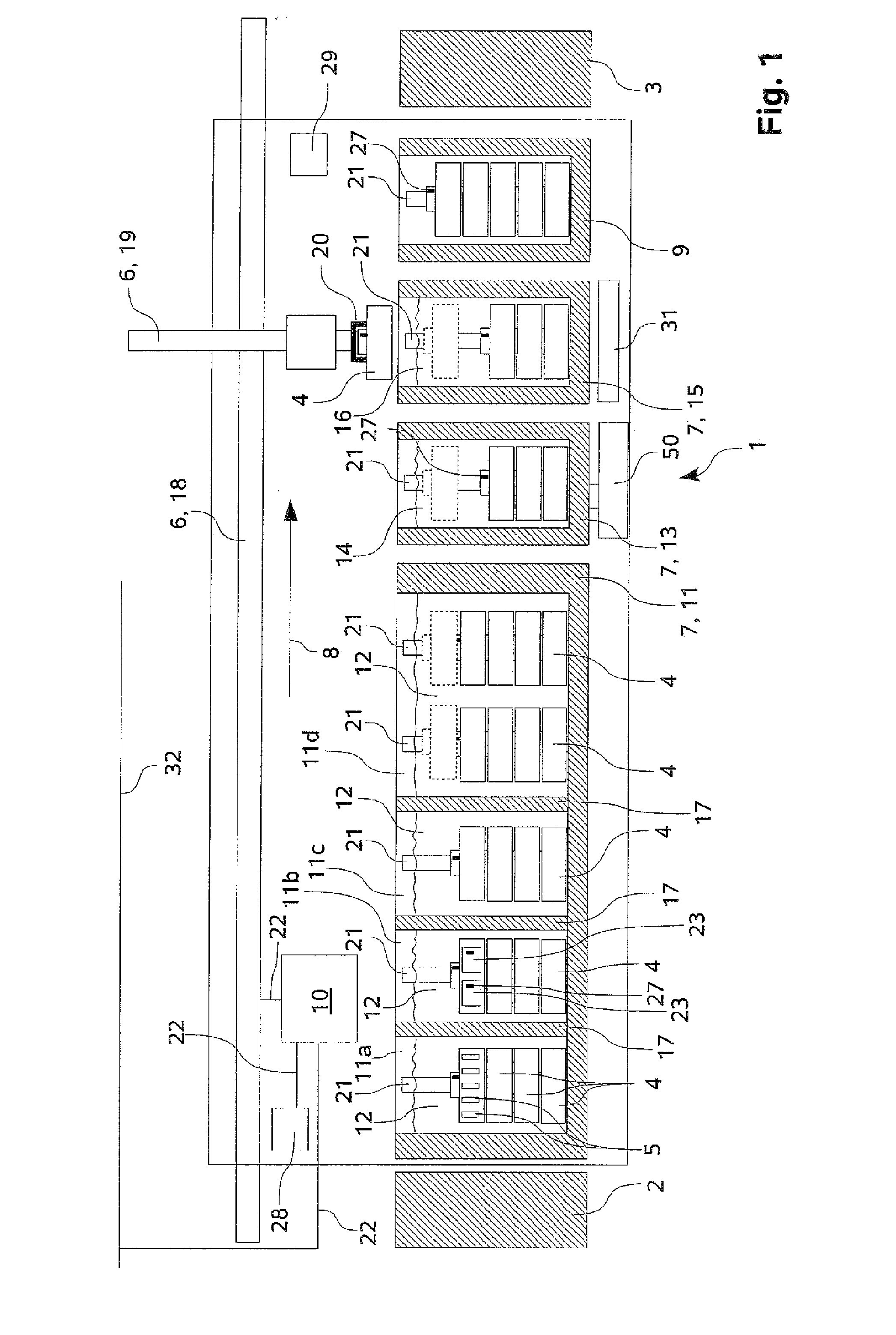
[0055]FIG. 1 shows an embodiment of an inventive tissue infiltration device 1. The tissue infiltration device 1 has an input station 2 and an output station 3. An operator can transfer a transport device 4 to the input station 2 of the tissue infiltration device 1. In a comparable manner, an operator can take a transport device 4 that has run through the tissue infiltration device 1 from the output station 3. Only schematically it is illustrated in one transport device4 that a transport device 4 can hold a plurality of cassettes 5, and in the embodiment according to FIG. 1, up to 60 cassettes 5 per transport device 4. The transport devices 4 shown in FIG. 1 have a circular base area, however, alternatively, they could also have a square base area. Basically, with the tissue infiltration device 1 from FIG. 1, also transport devices 4 with a circular and with a square bas...


PUM

PropertyMeasurementUnit
angular shapeaaaaaaaaaa
processing timeaaaaaaaaaa
dwell timeaaaaaaaaaa

Abstract

The present invention relates to a tissue infiltration device (1) for samples (34) contained in cassettes (5). The tissue infiltration device (1) comprises at least two liquid containers (7, 11a-11d, 13, 15) and a transport apparatus (6). A liquid (12, 14, 16) having a property that can be predetermined can be filled into a liquid container (7, 11a-11d, 13, 15). A plurality of cassettes (5) can be held by a transport device (4). Using the transport apparatus (6), a transport device (4) can be brought to a liquid container (7, 11a-11d, 13, 15) and/or moved away from a liquid container (7, 11a-11d, 13, 15). A sequence of operations (8) can be prescribed in which a transport device (4) runs through the liquid containers (7, 11a-11d, 13, 15) of the tissue infiltration device (1). So that an accelerated or priority processing of a transport device (4) is possible using the tissue infiltration device (1), but without using an additional liquid container (7, 11a-11d, 13, 15) provided only for this purpose, it is provided that at least two transport devices (4) can be brought into a liquid container (7, 11a-11d, 13, 15) above and/or next to one another, wherein said transport devices can have different dwell times in the liquid container (7, 11a-11d, 13, 15).

Description

CROSS-REFERENCE TO RELATED APPLICATIONS[0001]The present application is the U.S. National Stage of International Application No. PCT / EP2008 / 062320 filed Sep. 16, 2008, which claims priority of German Application No. 10 2007 044 116.0 filed Sep. 16, 2007. The present application claims priority benefit of said International Application No. PCT / EP2008 / 062320 and said German Application No. 10 2007 044 116.0.FIELD OF THE INVENTION[0002]The present invention relates to a tissue infiltration device for samples contained in cassettes, the tissue infiltration device comprising at least two liquid containers and a transport apparatus. A liquid having a property that can be predetermined can be filled into a liquid container. A plurality of cassettes can be held by a transport device. Using the transport apparatus, a transport device can be brought to a liquid container and / or moved away from a liquid container. A sequence of operations can be prescribed in which a transport device runs thro...

Claims


Application Information

Patent Timeline
Patent Type & Authority Applications(United States)
IPC IPC(8): C12M3/00
CPCY10T436/2575G01N1/31
Inventor ULBRICH, HERMANNKONRAD, MARCRICHTER, PETER
Owner LEICA BIOSYST NUSSLOCH
Why Eureka
Try Eureka