System and Method For Controlling The Temperature of A Temperature Controlled Drawer

a temperature control and drawer technology, applied in the field of refrigerator appliances, can solve the problems of undesirable or excessive cooling difficulty in maintaining the desired temperature within the drawer, and the temperature of the temperature control drawer may get too cold, and achieve the effect of increasing the temperature in the temperature control drawer

Active Publication Date: 2017-07-06
HAIER US APPLIANCE SOLUTIONS INC
View PDF2 Cites 2 Cited by
  • Summary
  • Abstract
  • Description
  • Claims
  • Application Information

AI Technical Summary

Benefits of technology

[0008]In a first exemplary embodiment, a refrigerator appliance is provided. The refrigerator appliance includes a cabinet defining a fresh food chamber and a door being rotatably hinged to the cabinet to provide selective access to the fresh food chamber. A sealed system including a compressor, an evaporator, and an evaporator fan positioned adjacent the evaporator may be configured for urging chilled air through the evaporator into the fresh food chamber. A temperature controlled drawer may be disposed within the fresh food chamber and a controller may be configured to selectively operate the evaporator fan when the compressor is not operating, such that the temperature in the temperature controlled drawer is increased.

Problems solved by technology

However, the location of the temperature controlled drawer within the fresh food chamber may lead to difficulty in maintaining a desired temperature within the drawer.
The evaporator may therefore be positioned immediately adjacent the temperature controlled drawer, and may cause undesirable or excessive cooling of the temperature controlled drawer.
As a result, the temperature controlled drawer may get too cold due to conduction from the fresh food evaporator.
These configurations require additional components, more complicated assembly, and increased cost.
Increased system complexity also leads to decreased reliability and increased service costs during the life of the refrigerator appliance.

Method used


Image

  • System and Method For Controlling The Temperature of A Temperature Controlled Drawer
  • System and Method For Controlling The Temperature of A Temperature Controlled Drawer
  • System and Method For Controlling The Temperature of A Temperature Controlled Drawer

Examples


Embodiment Construction

[0023]Reference now will be made in detail to embodiments of the invention, one or more examples of which are illustrated in the drawings. Each example is provided by way of explanation of the invention, not limitation of the invention. In fact, it will be apparent to those skilled in the art that various modifications and variations can be made in the present invention without departing from the scope or spirit of the invention. For instance, features illustrated or described as part of one embodiment can be used with another embodiment to yield a still further embodiment. Thus, it is intended that the present invention covers such modifications and variations as come within the scope of the appended claims and their equivalents.

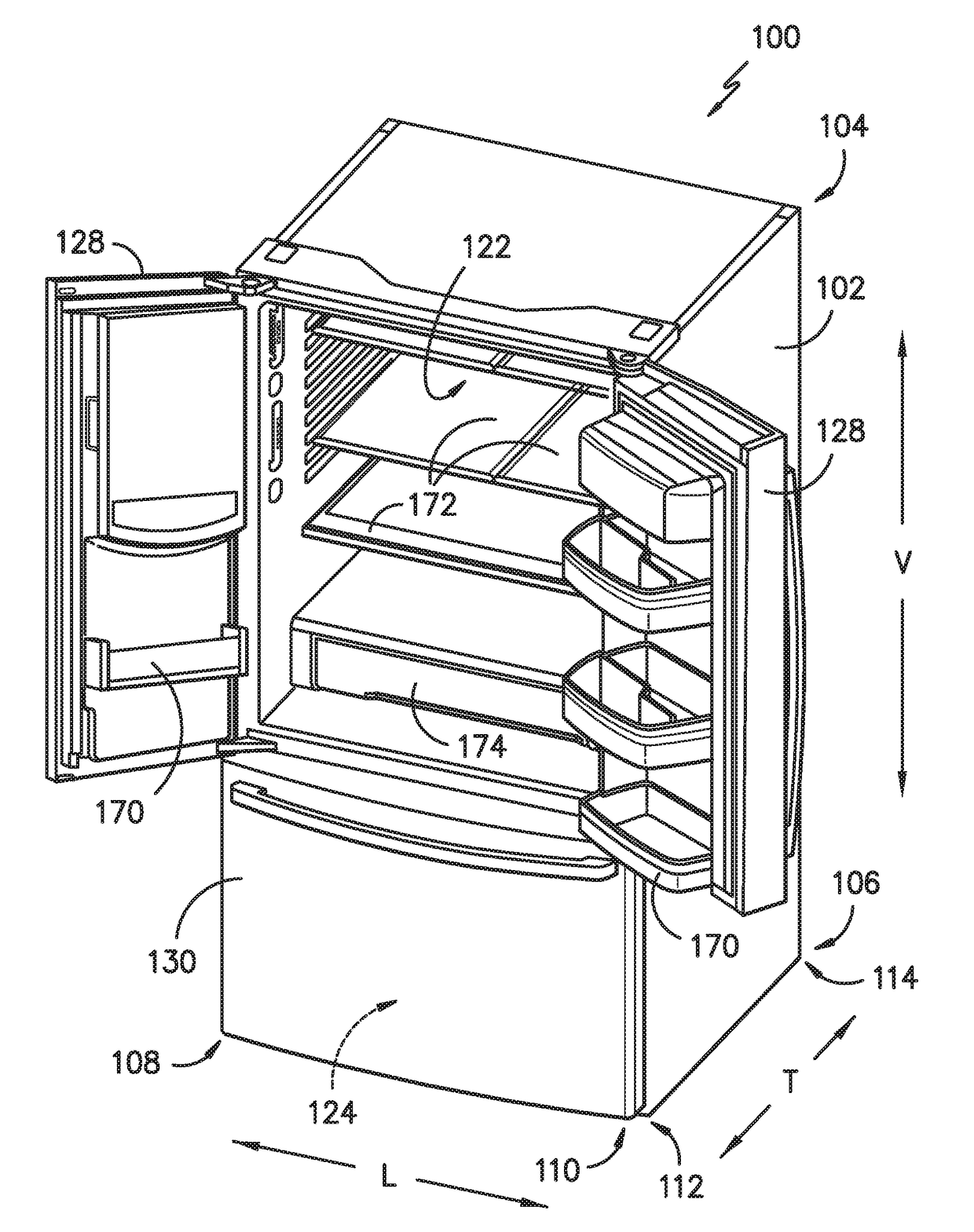
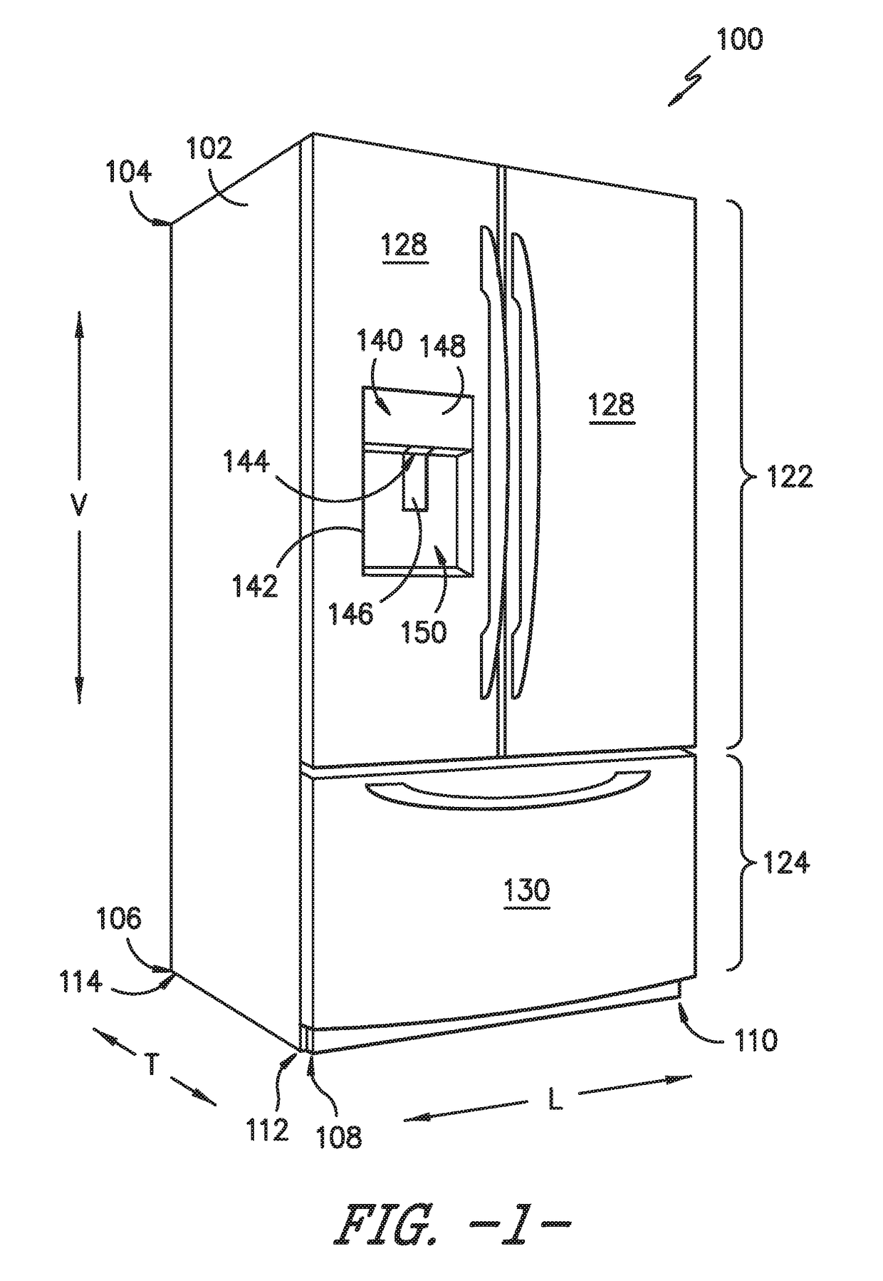
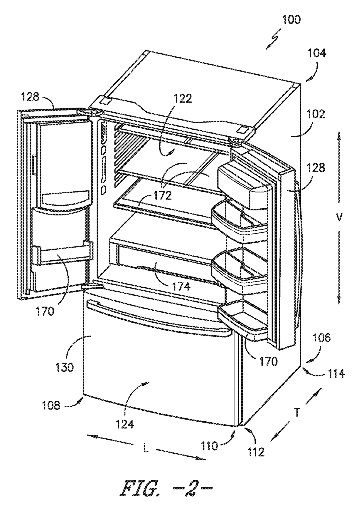
[0024]FIG. 1 provides a perspective view of a refrigerator appliance 100 according to an exemplary embodiment of the present subject matter. Refrigerator appliance 100 includes a cabinet or housing 102 that extends between a top 104 and a bottom 106 along a...


PUM


Abstract

A refrigerator appliance having a temperature controlled drawer with improved temperature control is provided. A sealed system including a compressor, an evaporator, and an evaporator fan may be configured for cooling the fresh food chamber. A controller is configured to operate the evaporator fan when the compressor is off in order to increase the temperature of the temperature controlled drawer. Additionally, or alternatively, a secondary fan may be attached to the temperature controlled drawer and may be selectively operated by the controller to circulate air from the chilled chamber through the temperature controlled drawer. In this manner, the temperature of the temperature controlled drawer may be more precisely controlled regardless of whether the compressor is running.

Description

FIELD OF THE INVENTION[0001]The present subject matter relates generally to refrigerator appliances, and more particularly to controlling the temperature of a temperature controlled drawer within such refrigerator appliances.BACKGROUND OF THE INVENTION[0002]Certain refrigerator appliances utilize sealed systems for cooling chilled chambers of the refrigerator appliances. A typical sealed system includes a compressor, a condenser, an expansion device, and an evaporator connected in series and charged with a refrigerant. The compressor continuously circulates refrigerant in the sealed system. In the condenser, hot, high pressure gas refrigerant condenses into liquid and expels heat. The liquid refrigerant passes through the expansion device where it rapidly expands and passes into the evaporator as a two-phase refrigerant. A fan may circulate air through the cold evaporator before delivering the cooled air through an opening into the chilled chamber. Air from the chilled chamber is ci...

Claims


Application Information

Patent Timeline
Patent Type & Authority Applications(United States)
IPC IPC(8): F25D17/06F25D23/00F25D29/00F25D11/02
CPCF25D17/065F25D11/02F25D29/00F25D23/00F25D17/067F25D25/02F25D2317/061F25D2317/0681F25D2317/0682F25D2700/121
Inventor DJEREKAROV, JIVKO OGNIANOVLI, JIANWUKYRIACOU, STEPHANOS
Owner HAIER US APPLIANCE SOLUTIONS INC
Why Eureka
Try Eureka