Heater control system with combination modular and daisy chained connectivity and optimum allocation of functions between base unit and local controller modules

a technology of heater control and modularity, applied in the field of heater control system, can solve the problems of inability to provide only limited temperature control, inability to meet the needs of applications, and high cost of individual heater failures, so as to improve individual heater temperature control equipment, reduce wiring complexity, and minimize physical size.

Inactive Publication Date: 2005-05-17
MKS INSTR INC
View PDF56 Cites 55 Cited by
  • Summary
  • Abstract
  • Description
  • Claims
  • Application Information

AI Technical Summary

Benefits of technology

[0013]A general object of this invention is to improve individual heater temperature control equipment for pipe heating systems that comprise a plurality of pipe heaters, while minimizing physical size, wiring complexity, and installation, maintenance, and removal inefficiencies.

Problems solved by technology

Further, because consequences of individual heater failures can be quite expensive due to down time for the manufacturing process to disassemble and clean or replace clogged or damaged pipes, valves, and other components, heater control systems should be able to provide the user with operating information during use, such as whether the heater is “on” or “off” and whether the heater is within a specified temperature range.
Unfortunately, such temperature controllers that utilize bimetallic or other snap-action or creep-action type thermostats generally have a single, fixed temperature set point and provide only limited temperature control.
In this regard, most snap-action electro-mechanical temperature controllers have a 15° C. or larger hysteresis or deadband around a set point temperature, which is unacceptable for applications that require tight pipe temperature control within only a few degrees of set point.
Creep-action thermostats offer tighter initial temperature control, but they then become inaccurate as they drift over time.
They also have short service lives due to high levels of electric arcing that occurs between their switch contacts.
Therefore, the general practice is to permanently embed the electro-mechanical temperature controller within the pipeline heater, and when the thermostat fails or needs servicing, the entire heater with controller must be replaced and typically scrapped.
Another problem with most electro-mechanical temperature controllers is that they provide little or no operating information during use, and to find a non-functioning heater, operating or maintenance personnel have to touch each of the heaters with their hands to determine if it is warm and therefore, presumably operating.
Additionally, the users of these heaters often are left without any accurate information on the actual operating temperature of the heater.
While such electronic temperature controllers, when combined with thermocouples, provide improved control of each heater and a tighter temperature range, they are relatively costly, and the large bundles of wires are cumbersome to install, especially in tight spaces.
The high cost per controller and tangle of wires has led many users to bundle several heaters together in a zone or piping portion and to place the entire zone under the control of a single controller.
While that solution decreases the complexity and tangle of wires, it also results in all the pipe heaters in a zone being set to a single temperature and, of course, the accuracy of control decreases with the overall size of the zone.
Also, there is no way to ensure that individual slave heaters in a zone do not run arbitrarily hotter or colder than the master heater, which leads to decreased accuracy or tightness in controlling the temperature throughout the piping system or zone.
The use of a single controller to operate an entire zone may also create safety issues.
In other words, if the slave heaters are not properly controlled within the zone, and thermal “run away” can result in blown fuses and / or fires, which cause safety hazards and significant down time within the manufacturing facility.
Additionally, the central controllers for systems in which a central controller is wired to control many individual heaters are relatively large, e.g., 48 mm by 96 mm by 100 mm and must be located remote from the heaters due to space and mounting constraints within the typical industrial setting.
The size of each central controller becomes more of a problem in practice because a protective cage is often placed around the controller to protect sensitive electronic components from inadvertent damage from high temperature sources and physical contact.
Further, installation and maintenance of the remotely-located central controllers for a large number of individual heaters are problematic because of the number of wires that must be run between the central controller and each heater.
For safety and convenience, these wires are often strapped or bundled together, which makes it harder for maintenance personnel to work on a single heater, yet unbundling leaves an even more undesirable tangle of wires.
Such “rat's nest” of wiring in the piping system makes maintenance, upgrading, and troubleshooting of these heater control systems time consuming and difficult for operating and maintenance personnel.

Method used


Image

  • Heater control system with combination modular and daisy chained connectivity and optimum allocation of functions between base unit and local controller modules
  • Heater control system with combination modular and daisy chained connectivity and optimum allocation of functions between base unit and local controller modules
  • Heater control system with combination modular and daisy chained connectivity and optimum allocation of functions between base unit and local controller modules

Examples


Embodiment Construction

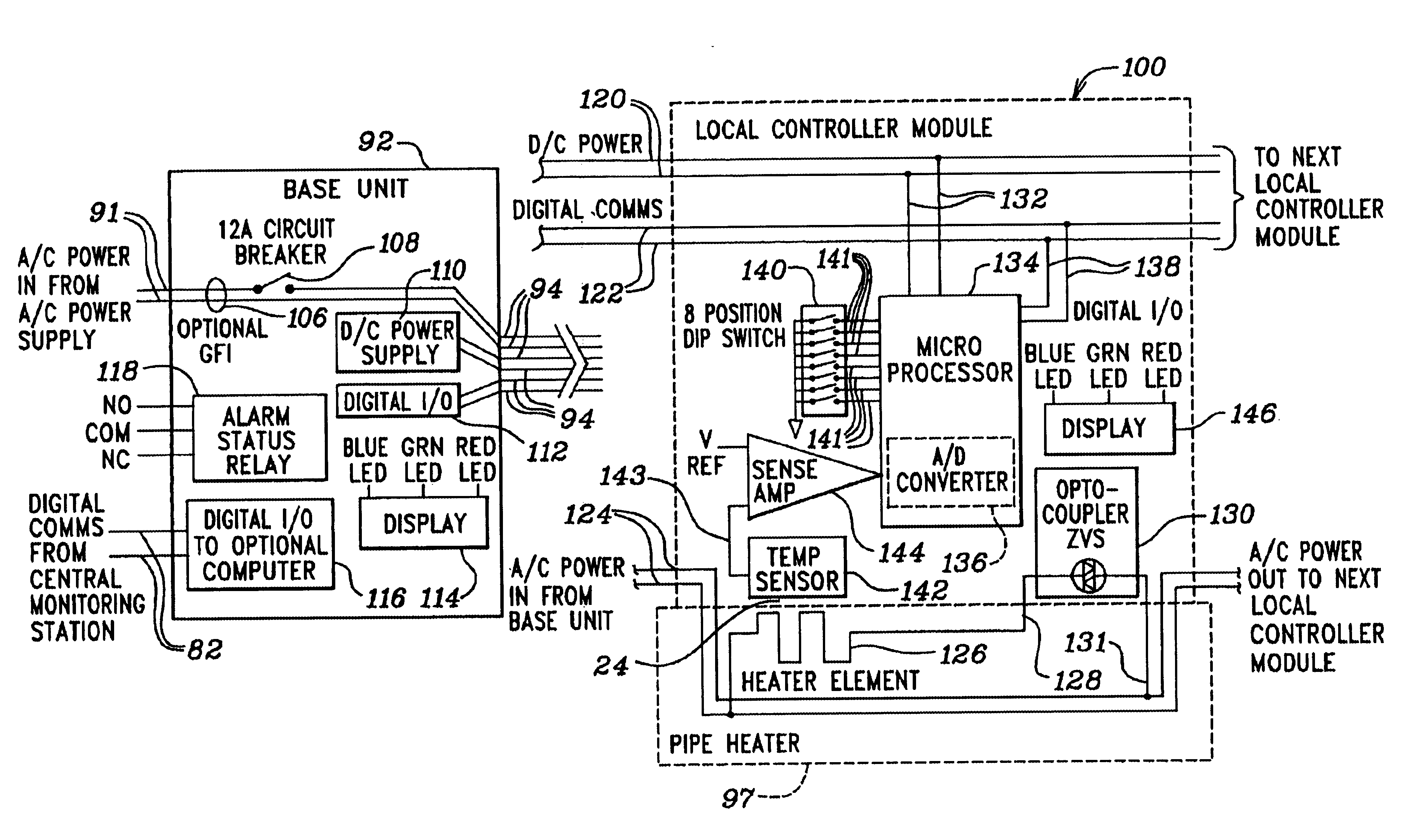
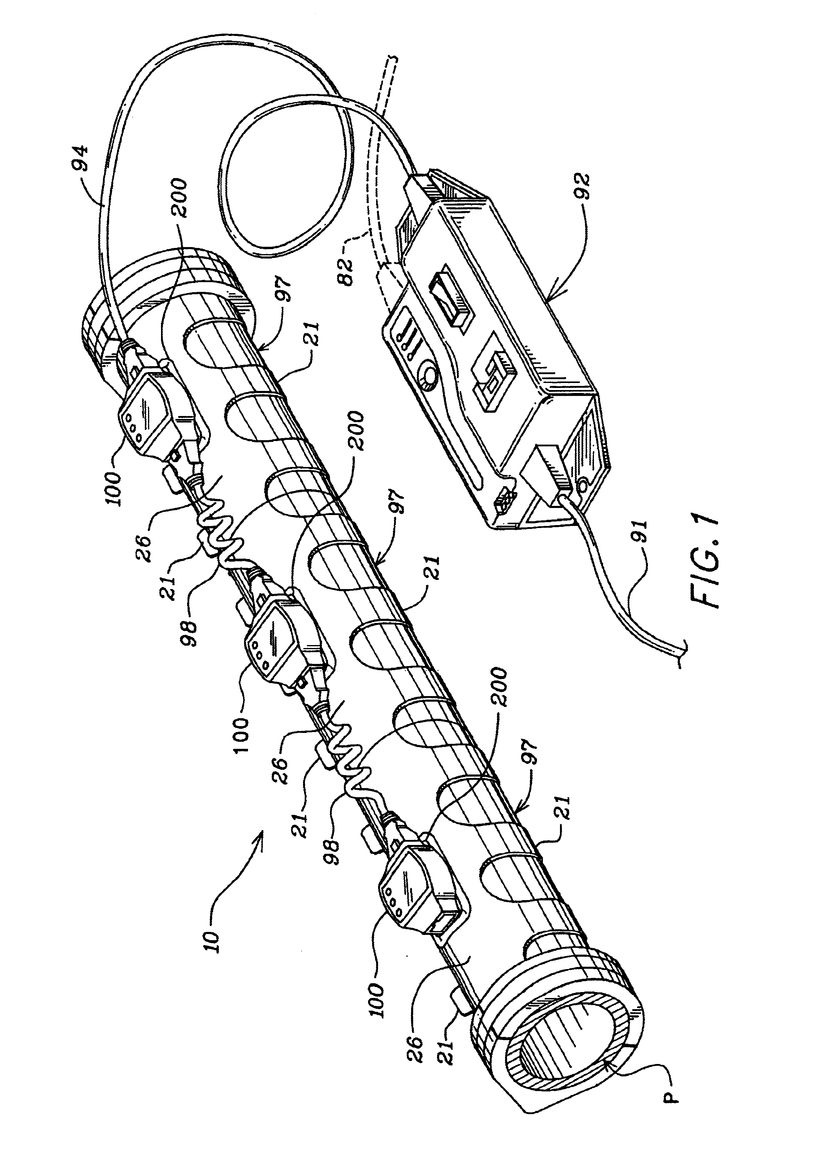
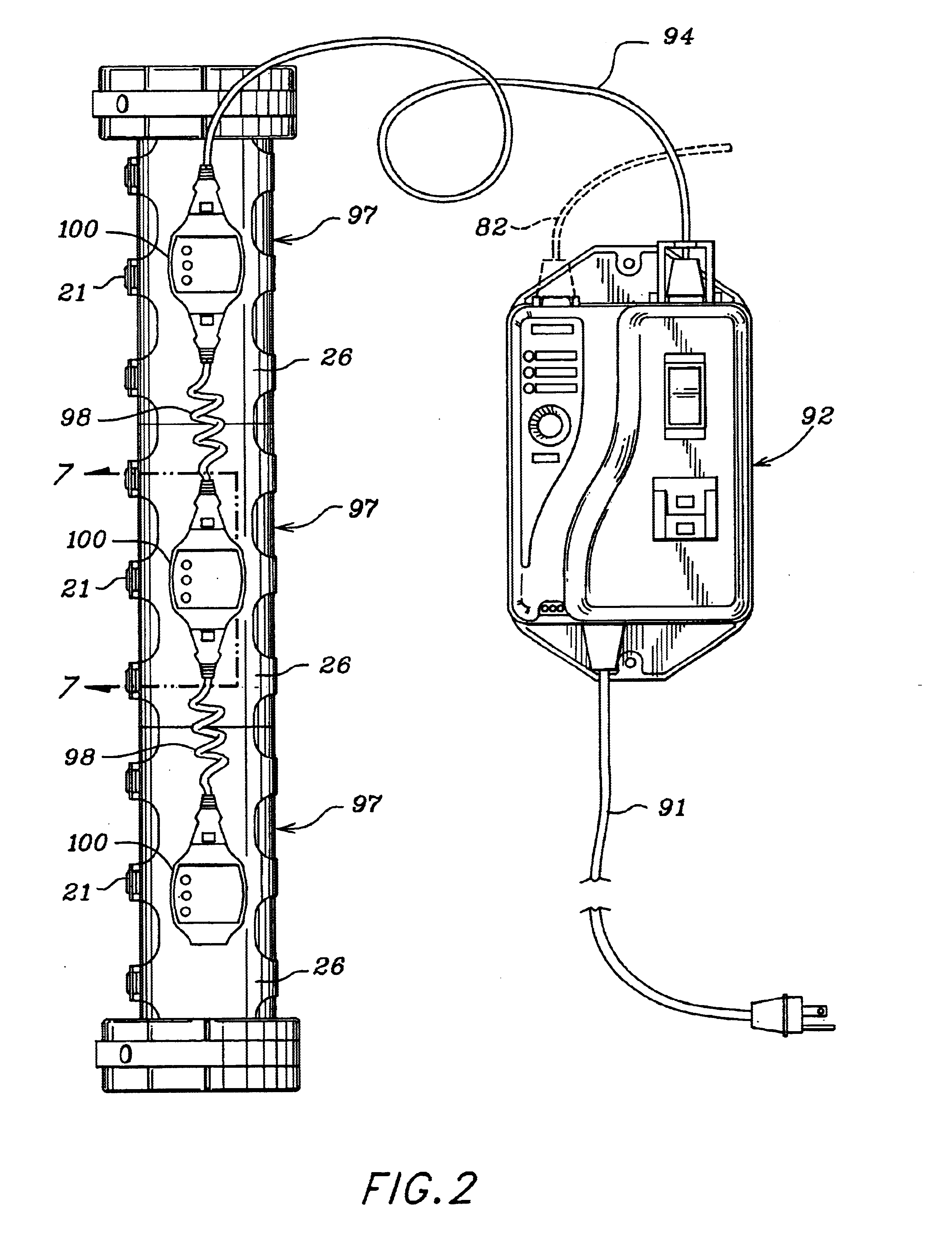
[0036]A pipe heater control system 10 according to this invention is shown in FIGS. 1 and 2 with an example of three of the local controller units 100 of this invention mounted on three pipe heaters 97 in a daisy chain connection to a base unit 92. The three pipe heaters 97 are mounted on a pipe P to be heated in a typical manner, for example, as described in U.S. Pat. No. 5,714,738 issued to Hauschulz et al., which describes the structures, materials, and uses of such pipe heaters and is incorporated herein by reference for all that it discloses. While some of the pipe heater 97 structural details will be described below, suffice it to say at this point that each pipe heater 97 can be secured on the pipe P by one or more straps 21. The pipe heaters 97 and local controller modules 100 are connected together in daisy chain fashion by daisy chain cords 98, which will be described in more detail below. The first pipe heater 97 and local controller module 100 in the daisy chain are conn...


PUM


Abstract

A heater control system that utilizes electronic temperature control at each of a number of interconnected heaters is provided for monitoring and operating heaters within a narrow temperature range. In one embodiment, a heater control system is provided that is adapted for controlling a number of heaters positioned on pipe and components of a piping system from a remote location. The heater control system includes satellite controllers mounted on each heater connected daisy chain fashion and includes a monitoring station with a user interface for allowing a user to monitor and to remotely control the operating status or temperature of each heater in the heater control system. To satisfy the user's space requirements, the size of each controller is maintained at a small form factor and a single cord is used to provide power and communications lines to and between the controllers. Each controller integrates power supply and control with electronic temperature control to minimize the use of mechanical switching and to increase the accuracy of temperature control. The temperature set point is adjustable at each controller and, in one embodiment, the temperature set point is remotely adjustable from a remote monitoring station. The operating status of each controller is displayed on the exterior of the controller's housing and in one embodiment, the operating status, such as temperature, is displayed at a base station for each line of controllers and heaters and on a user interface monitor at a monitoring station.

Description

CROSS-REFERENCE TO RELATED APPLICATIONS[0001]This patent application is a continuation-in-part of U.S. patent application Ser. No. 09 / 553,416, filed Apr. 20, 2000 now abandoned.BACKGROUND OF THE INVENTION[0002]1. Field of the Invention[0003]The present invention relates generally to a system for controlling and monitoring the temperature of heaters, and more particularly, to a heater control system for a plurality of individual pipe heaters positioned adjacent each other on a pipe with a like number of controller modules, which are configured for daisy chain connection together and for individual connection to individual mounting on and pipe heaters to provide individual electronic temperature and power control at each of the pipe heaters.[0004]2. Description of the Related Art[0005]The use of pipe heaters is widespread in semiconductor manufacturing, chemical, and pharmaceutical processing, plastics manufacturing, food processing, and other industries to heat piping systems to cont...

Claims


Application Information

Patent Timeline
Patent Type & Authority Patents(United States)
IPC IPC(8): G05D23/19
CPCG05D23/1935G05D23/1934H05B3/58
Inventor HAUSCHULZ, DANA S.
Owner MKS INSTR INC
Why Eureka
Try Eureka