Variable gain optical amplifiers

Active Publication Date: 2007-11-15
II VI DELAWARE INC
View PDF8 Cites 15 Cited by
  • Summary
  • Abstract
  • Description
  • Claims
  • Application Information

AI Technical Summary

Benefits of technology

[0024] In one embodiment of the invention the feed forward means includes variable filter means for adjusting a digital sampling rate of the feed forward signal. Also the feed back means may include variable filter means for adjusting a digital sampling rate of the feed back sig

Problems solved by technology

Unless control electronics are used to maintain a steady inversion level under various operating conditions, the gain of EDFA stages will be subject to unacceptable transients.
Gain transients in an amplifier may cause fluctuations in the power of the output signals from the amplifier.
If the output signals are too weak, it may not be possible to detect the signals.
If the output signals are too strong, the signals may be subject to nonlinear optical effects in the fibre.
This shows that the gain profile of the amplifier varies with the pump drive conditions, and therefore that external conditions, such as the adding or dropping of channels, can result in undesirable power transients.
Such a known AGC suffers from the main limitation in use that it has too slow a response time with the result that, for example, a required adjustment of the pum

Method used


Image

  • Variable gain optical amplifiers
  • Variable gain optical amplifiers
  • Variable gain optical amplifiers

Examples


Example

DETAILED DESCRIPTION OF THE DRAWINGS

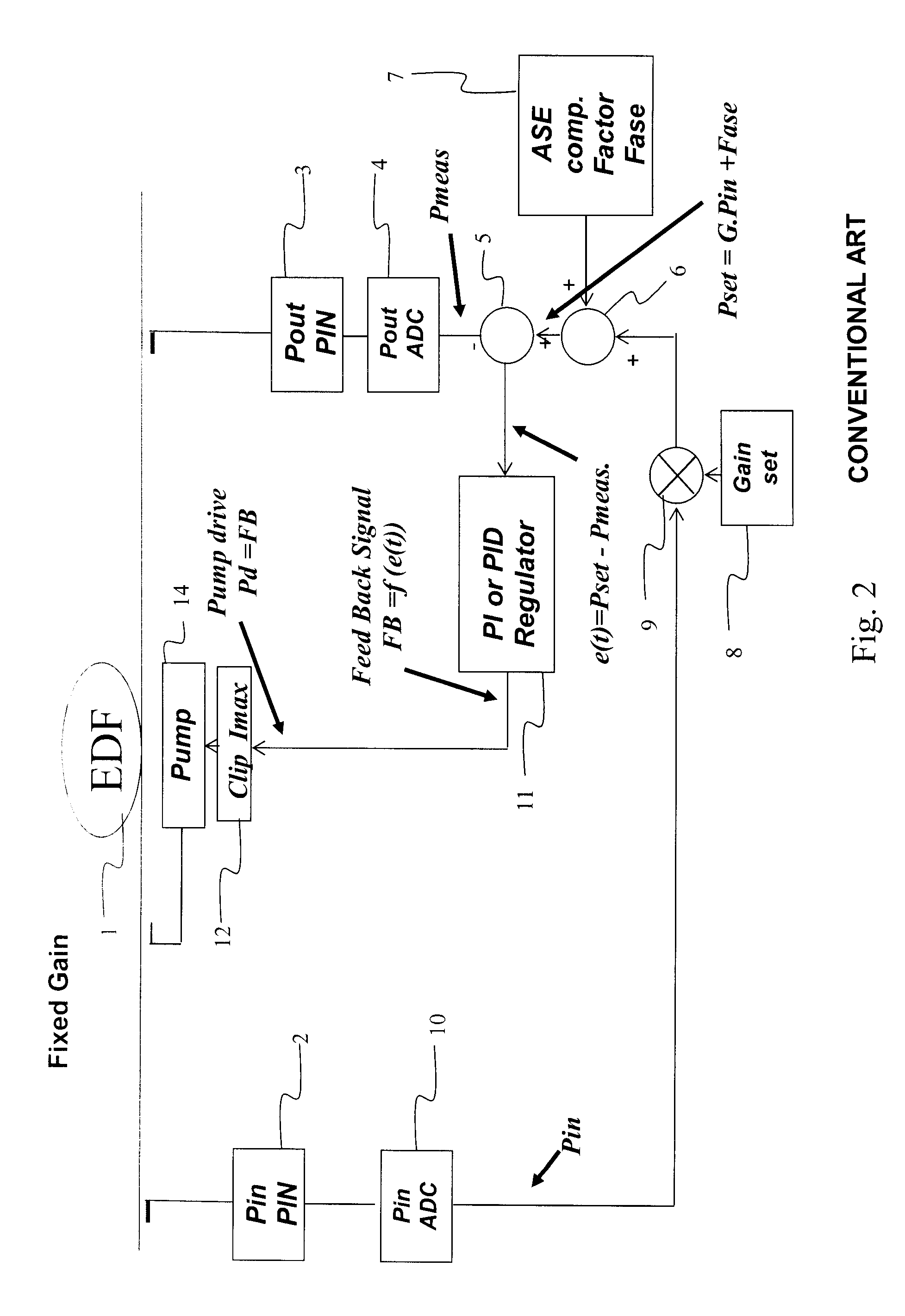
[0032] Each of the embodiments of the invention to be described below is applied to an EDF loop amplifier comprising one or more EDF loops. The or each EDF loop 1 is supplied with pump light from a pump driver in the form of a laser diode 4 under the control of an AGC. If required more than one laser diode may be provided for pumping the or each EDF loop, and / or additional loops and associated pump laser diodes may be provided. The pump stages are controlled in response to receipt by the AGC of electrical detection signals from input and output power detectors 2 and 3 in the form of photodiodes and associated tap-off couplers for monitoring the input and output powers Pin and Pout of the amplifier.

[0033] Considering first the embodiment of FIG. 4, the output signal from the output power detector 3 is supplied to an ADC 4 which in turn supplies an output signal Pmeas indicative of the measured power output signal to one input of a comparator 5, a...


PUM


Abstract

A variable gain optical amplifier comprises an EDFA for amplifying optical signals at different wavelengths and a pump driver 14 for optically pumping the EDFA to provide optical gain. An input detector 2 is provided for monitoring the power Pin of input signals to the EDFA, and an output detector 3 is provided for monitoring the power Pout of output signals from the EDFA. A gain control arrangement is provided for supplying a drive signal to the pump driver 14 to control the optical gain including a feed forward arrangement 20, 21, 22, 23 for supplying a feed forward signal dependent on the monitored input power Pin, and a feed back arrangement 5, 6, 7, 8, 9, 30 for supplying a feed back signal dependent on the monitored output power Pout. In order to ensure rapid gain control the feed back arrangement comprises an adaptive proportional-integral (PI or PID) controller 30 for controlling the optical gain at a required gain set point in accordance with proportional and integral control coefficients Kp and Ki corresponding to a required gain profile, at least one of which is dynamically variable in dependence on the monitored output power Pout, the output signal from the controller 30 and the feed forward signal being added in an adder 31 to produce the drive signal for the pump driver 14.

Description

[0001] This invention relates to variable gain optical amplifiers and is concerned more particularly, but not exclusively, with erbium doped fibre amplifiers (EDFAs). BACKGROUND OF THE INVENTION [0002] In optical networks that use dense wavelength division multiplexing (DWDM), multiple wavelengths of light are used to support multiple communications channels on a single fibre. Optical amplifiers are used in such networks to amplify optical signals that have been subject to attenuation over multi-kilometre fibre-optic links. A typical amplifier may include EDFA components that are pumped with diode lasers. The EDFA stages increase the strength of the optical signals being transmitted over the fibre-optic links. It is known for such amplifiers to include automatic gain control (AGC) for providing a constant gain regardless of variation in the input power and the wavelength composition of the amplifier input. [0003] The gain of EDFA stages depends on the inversion level of erbium ions ...

Claims


Application Information

Patent Timeline
IPC IPC(8): H04B10/08
CPCH01S3/06754H01S3/1301H01S3/10007H04B10/2931H01S3/10015H01S3/1305H01S3/1608H01S2301/02H01S3/13013
Inventor MCCLEAN, IAN PETERFOURTE, STEPHEN DAVIDDRAKE, JONATHON STUARTFLINTHAM, BARRIE
Owner II VI DELAWARE INC
Why Eureka
Try Eureka