[0017]It is an
advantage of the present invention that the decision unit is used to calculate the difference between the first binary signal NRZ1 and the second binary signal NRZ2 in a predetermined time period, and then switching either the maximum likelihood detector (e.g.
Viterbi decoder) or the non-maximum likelihood detector (e.g. data slicer) based on the calculation of the difference, and executing data recovery is performed. Consequently, properly switching the current maximum-likelihood detector and non-maximum-likelihood detector is a solution to improve data recovery efficiency, without designing a new complex maximum-likelihood detector.
[0018]These and other objectives of the present invention will no doubt become obvious to those of ordinary skill in the art after reading the following detailed description of the preferred embodiment, which is illustrated in the various figures and drawings.DETAILED DESCRIPTION OF THE PREFERRED EMBODIMENT
[0019]Please refer to FIG. 1, which is a
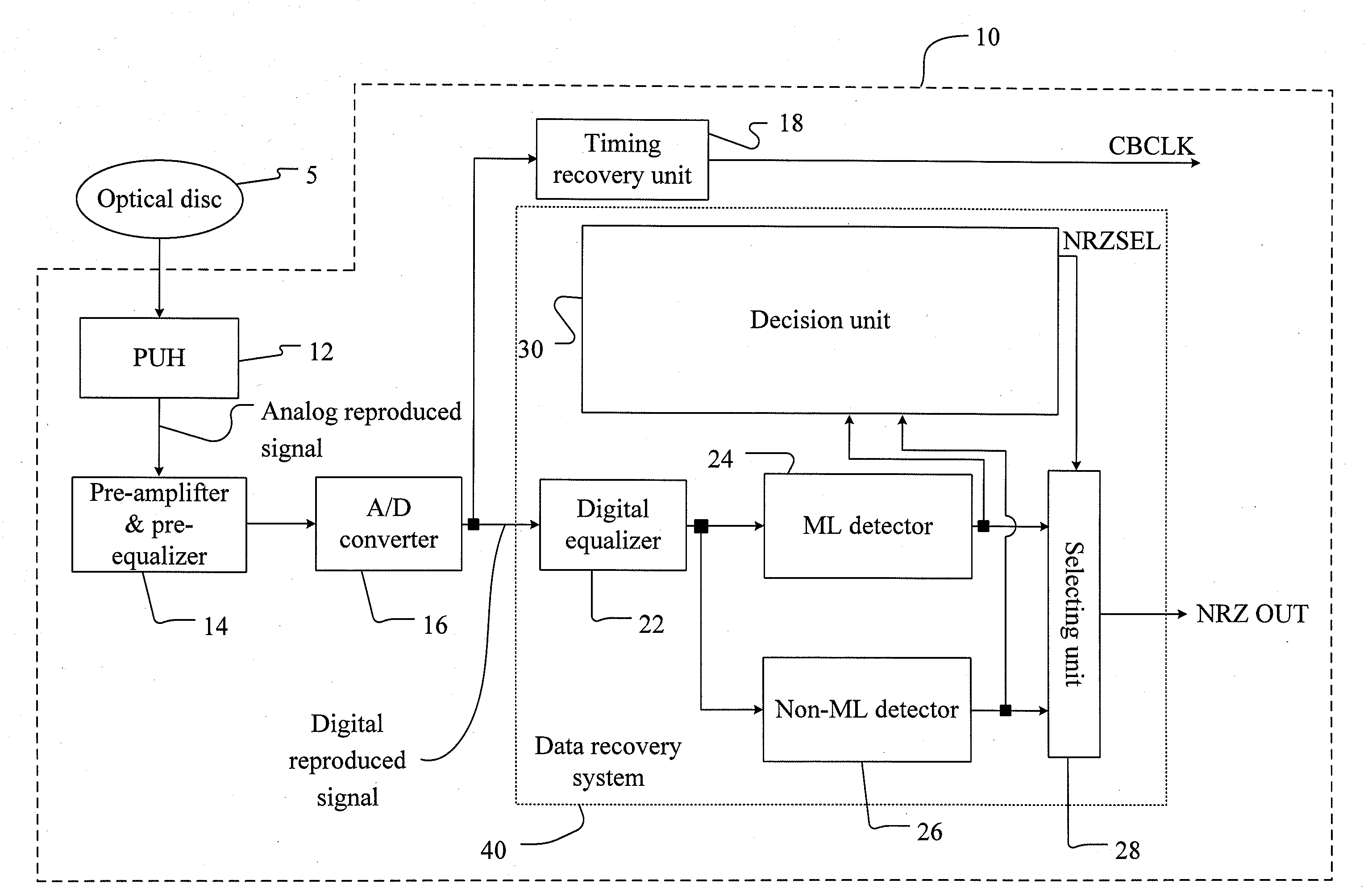
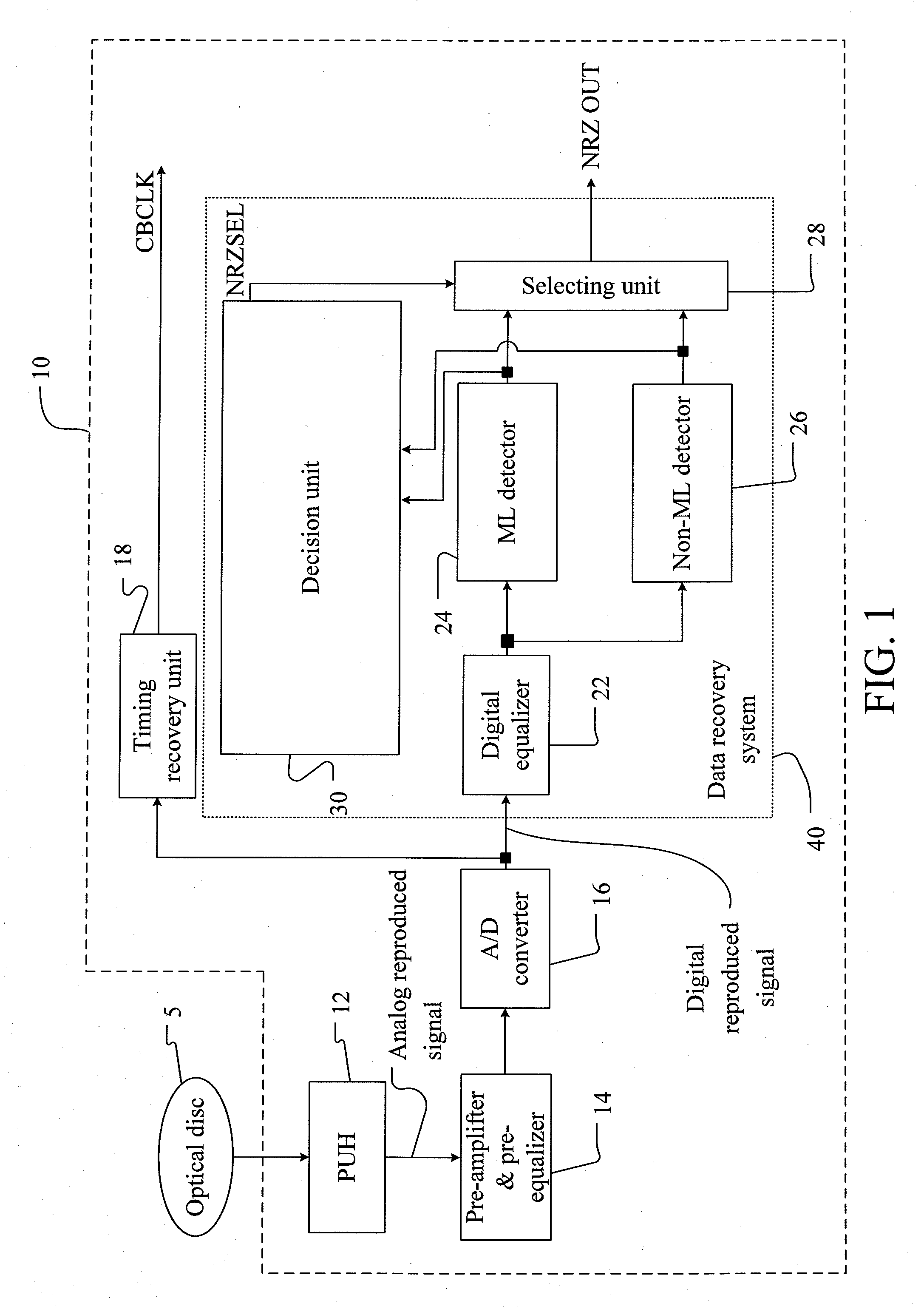
functional block diagram of a preferred embodiment of a data recovery system 40 according to the present invention. The data recovery system 40 can be applied in an optical drive 10. A
pickup head 12 of the optical drive 10 emits
light beam toward an optical disc 5, and produces analog reproduced signal based on reflective
light beam from the optical disc 5. The analog reproduced signal is then fed into a pre-
amplifier and a pre-
equalizer 14 respectively, which are used for adjusting
gain control to make magnitude of the analog reproduced signal complying with an input range of an
analog to digital converter (A / D converter) 16, and for filtering out high-
frequency noise and low-frequency
jitter of the analog reproduced signal. Thereafter, the A / D converter 16 transforms the analog reproduced signal into digital reproduced signal.
[0020]Digital reproduced signal is then fed into a data recovery system 40 and a timing recovery unit 18 for recovering a channel bit
clock (CBCLK) which is used for synchronization of digital reproduced signal. The
clock signal of both the analog-to-
digital converter 16 and the data recovery system 40 follows the channel bit
clock (CBCLK).
[0021]In this preferred embodiment, the data recovery system 40 comprises a digital
equalizer 22, a maximum likelihood detector (ML detector) 24, a non-maximum likelihood detector (non-ML detector) 26, a selecting unit 28, and a decision unit 30. The ML detector 24 may be a
Viterbi decoder, and the non-ML detector 26 may be a data slicer. For simplicity reason, operation principles of either the Viterbi decoder or the data slicer is aware by the skilled person in this art, therefore, no further detail is described hereinafter. The ML detector 24 and the non-ML detector 26 respectively convert the digital equalized signal into a first binary signal and a second binary signal (hereinafter referred to as NRZ1 and NRZ2). It is noted that the ML detector 24 and the non-ML detector 26 employ respective algorithms to convert the identical digital equalized signal into two kinds of slightly different binary signals. In general, the binary signals are selected from a group consisting of non-return-to-zero (NRZ) signals and non-return-to-zero inverted (NRZI) signals. For
clarity, non-return-to-zero signals are introduced in the following embodiments according to the present invention. The decision unit 30 detects differences between the first non-return-to-zero signal (NRZ1) generated by the ML detector 24, and the second non-return-to-zero signal (NRZ2) generated by the non-ML detector 26 in a predetermined time period. Also the decision unit 30 outputs a selecting signal NRZSEL to a selecting unit 28 in response to an amount of the detected differences. Finally, the selecting unit 28 selectively outputs the first non-return-to-zero signal NRZ1 from the ML detector 24 or the second non-return-to-zero signal NRZ2 from the non-ML detector 26 based on the selecting signal NRZSEL.
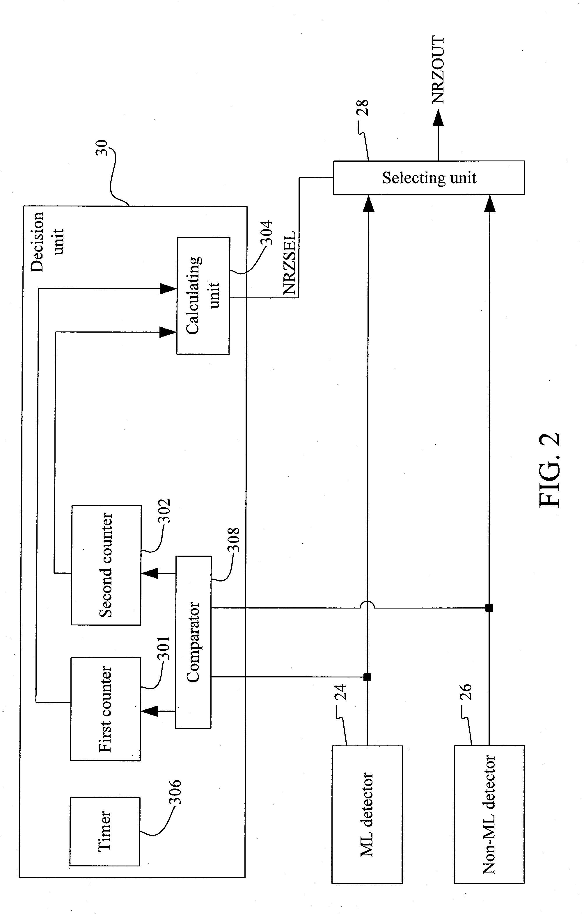
[0022]Please refer to FIGS. 2 and 3. FIG. 2 is a
functional block diagram of a preferred embodiment of the decision unit 30 depicted in FIG. 1. FIG. 3 is a
flowchart of a preferred embodiment method incorporating the decision unit 30 depicted in FIG. 2. The decision unit 30 comprises a first counter 301, a second counter 302, a calculating unit 304, a
timer 306, and a
comparator 308. First of all, the first counter 301, the second counter 302, and the
timer 306
return to zero (as in Step S202) to get ready for counting an amount of differences between the first non-return-to-zero signal NRZ1 and the second non-return-to-zero signal NRZ2 in a predetermined time period. The
timer 306 which can be implemented by a counter sequentially sums a counting value NRZCnt associated with a period cycle of the channel bit clock CBCLK (NRZCnt=NRZCnt+1, as in Step S204) until the counting value NRZcnt matches a predetermined value LEVEL_A (Step S206). As long as the counting value NRZcnt matches the predetermined value LEVEL_A, it indicates that the predetermined time period is up. In this preferred embodiment, the predetermined value LEVEL_A can be set to 4 8192T, where T indicates the period cycle of the channel bit clock (CBCLK).

