Magnetically coupled device and electronic equipment employing same

a technology of electromagnetic coupling and electronic equipment, applied in the direction of relays, fixed transformers or mutual inductances, instruments, etc., can solve the problems of preventing normal communication and output signal waveforms, and achieve the effect of reducing the signal component(s) of dummy coils

Inactive Publication Date: 2007-03-20
SHARP KK
View PDF7 Cites 6 Cited by
  • Summary
  • Abstract
  • Description
  • Claims
  • Application Information

AI Technical Summary

Benefits of technology

[0009]Magnetically coupled devices in accordance with such embodiment(s) of the present invention are such that transmitting coil(s) and receiving coil(s) are mutually magnetically coupled, signal(s) being transmitted from transmitting coil(s) to receiving coil(s). Moreover, dummy coil(s) may be arranged more or less in vicinity or vicinities of receiving coil(s), and difference(s) between or among receiving coil signal(s) and dummy coil signal(s) may be determined. Such arrangement of dummy coil(s) may permit weakening of magnetic coupling between or among dummy coil(s) and transmitting coil(s), and may permit equivalent external magnetic field(s) to be detected at both receiving coil(s) and dummy coil(s). Dummy coil output(s) would therefore contain almost no signal component(s) generated due to magnetic field(s) from transmitting coil(s), but would contain noise component(s) generated due to external magnetic field(s). On the other hand, receiving coil output(s) would contain high levels of signal component(s) generated due to magnetic field(s) from transmitting coil(s), and would contain noise component(s) generated due to external magnetic field(s) in more or less equivalent fashion as compared with that at dummy coil(s). This being the case, by determining difference(s) between or among receiving coil signal(s) and dummy coil signal(s), it is possible to at least partially cancel out noise component(s) due to external magnetic field(s) and to extract signal component(s) due to transmitting coil magnetic field(s) with almost no loss. As a result, it is possible to reduce effects of external noise and stably carry out high-speed communication between or among transmitting coil(s) and receiving coil(s).
[0011]Thus, magnetically coupled devices in accordance with such embodiment(s) of the present invention are provided with one or more first dummy coils; and one or more second dummy coils; wherein at least one of the first dummy coil or coils or at least one of the second dummy coil or coils is provided with at least one shield member for at least partially blocking at least one external magnetic field. Shield member(s) may, for example, be provided at second dummy coil(s). In such a case, second dummy coil output(s) would contain almost no noise component(s) due to external magnetic field(s) and almost no signal component(s) due to magnetic field(s) from transmitting coil(s), but would contain substantially only internal noise component(s). This being the case, by determining difference(s) between or among receiving coil signal(s) and second dummy coil signal(s), it is possible to substantially eliminate internal noise component(s) contained within receiving coil signal(s). Alternatively or in addition thereto, by determining difference(s) between or among receiving coil signal(s) and first dummy coil signal(s), it is possible as previously mentioned to substantially eliminate noise component(s) due to external magnetic field(s) which is / are contained within receiving coil signal(s). By carrying out appropriate logic operation(s) on respective receiving coil signal(s) from which internal noise component(s) and / or noise component(s) due to external magnetic field(s) has or have been substantially eliminated in such fashion, it is possible to reduce internal noise component(s) and / or noise component(s) due to external magnetic field(s), and to satisfactorily extract signal component(s) due to transmitting coil magnetic field(s).
[0013]Thus, in magnetically coupled devices in accordance with embodiment(s) of the present invention, receiving coil(s) may be disposed between first dummy coil(s) and second dummy coil(s). Alternatively or in addition thereto, one or more embodiments of the present invention may comprise a plurality of dummy coils; wherein respective dummy coils and receiving coil(s) are arranged such that respective distances separating respective dummy coils from receiving coil(s) are substantially the same. This being the case, respective dummy coil(s) will permit more or less accurate detection of external magnetic field(s) detected by receiving coil(s).
[0015]Thus, in magnetically coupled devices in accordance with embodiment(s) of the present invention, number(s) of turn(s) of receiving coil(s) and number(s) of turn(s) of dummy coil(s) may be substantially identical. This will make it possible to cause receiving coil noise component(s) due to external magnetic field(s) and dummy coil noise component(s) due to external magnetic field(s) to be set to equivalent level(s), making it possible to definitively cause noise component(s) due to external magnetic field(s) to be canceled out through determination of difference(s) between or among receiving coil output(s) and dummy coil output(s).
[0017]Thus, in magnetically coupled devices in accordance with embodiment(s) of the present invention, because antimagnetic member(s) is / are provided between receiving coil(s) and dummy coil(s), dummy coil(s) may be at least partially shielded from magnetic field(s) of transmitting coil(s). This being the case, it will be possible to adequately reduce dummy coil signal component(s) due to transmitting coil magnetic field(s); and by determining difference(s) between or among receiving coil output(s) and first dummy coil output(s), it will be possible to extract signal component(s) due to transmitting coil magnetic field(s) with almost no loss.

Problems solved by technology

However, the foregoing conventional magnetoresistive devices have had the problem that, even where it may have been possible to reduce internal noise, as no consideration had been made for reduction of geomagnetism and other such external noise, there has been occurrence of distortion of output signal waveform(s) and / or phenomena such as dropped bits during communication of output signal(s), preventing normal communication.

Method used


Image

  • Magnetically coupled device and electronic equipment employing same
  • Magnetically coupled device and electronic equipment employing same
  • Magnetically coupled device and electronic equipment employing same

Examples


embodiment 1

[0032](Embodiment 1)

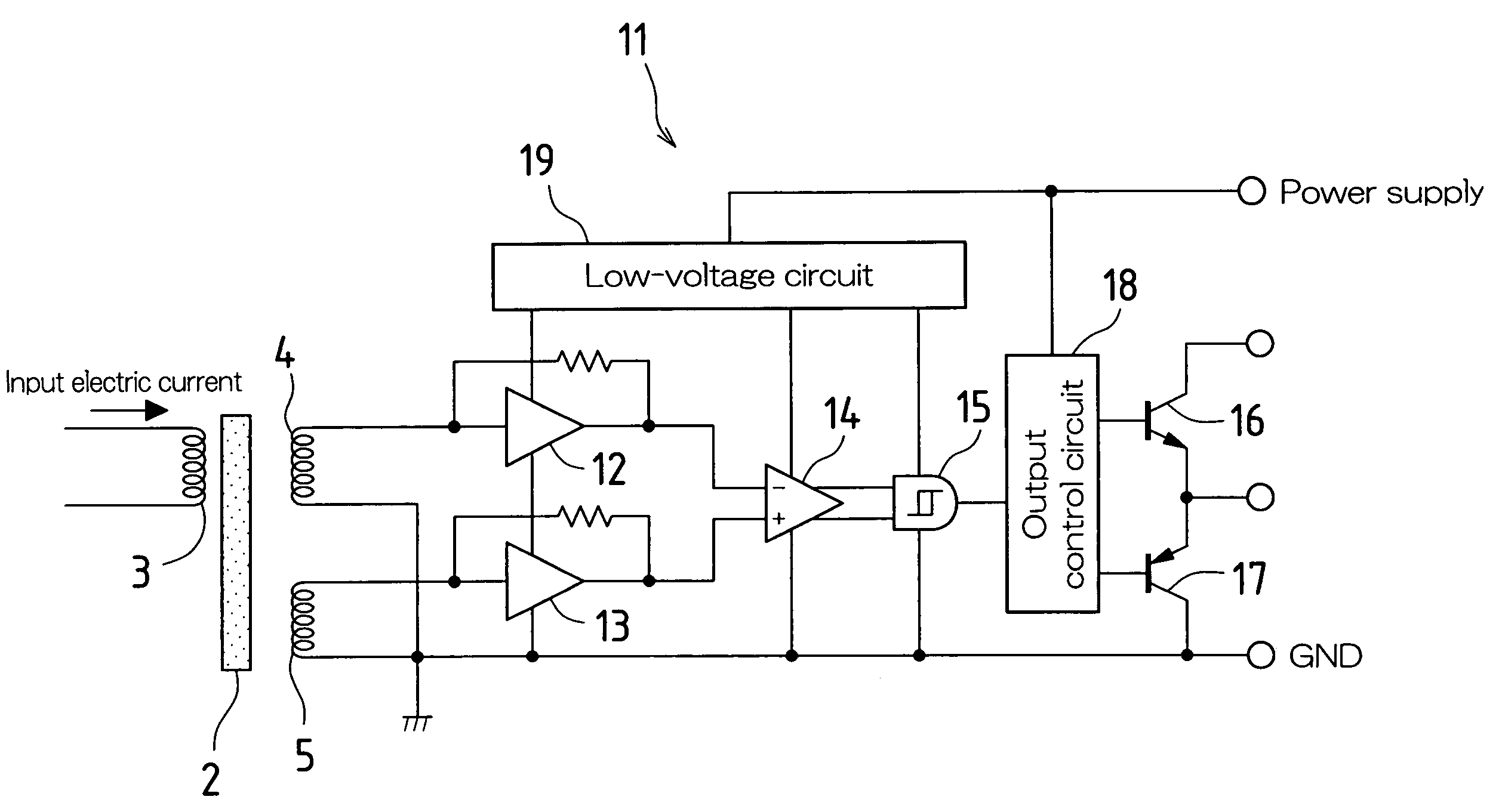
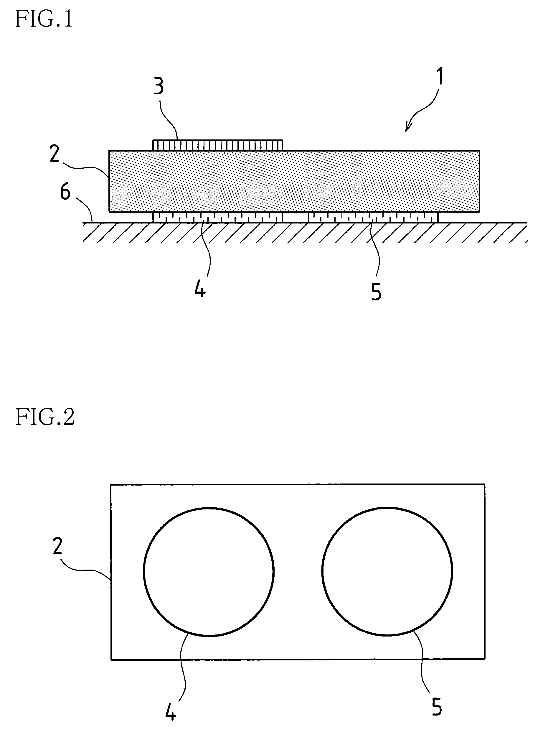
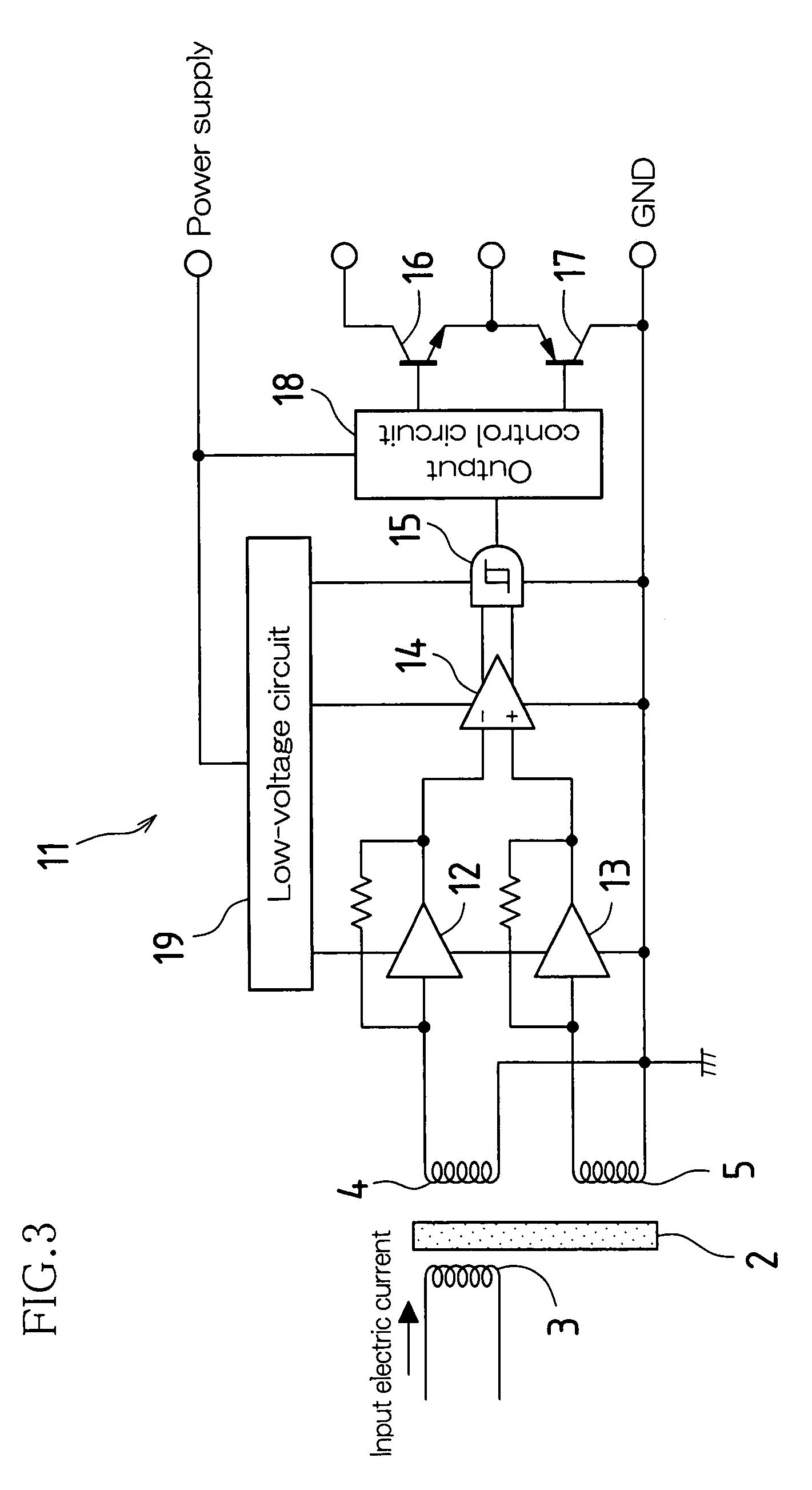
[0033]FIGS. 1 and 2 are a side view and a bottom view showing in schematic fashion a first embodiment of a magnetically coupled device in accordance with the present invention. Magnetically coupled device 1 of the present embodiment, present on receiving chip 6, is provided with insulator layer 2; transmitting coil 3 which is disposed above insulator layer 2; and receiving coil 4 and dummy coil 5 which are disposed beneath insulator layer 2.

[0034]Transmitting coil 3 and receiving coil 4 are stacked one atop the other with insulator layer 2 intervening therebetween, and are mutually magnetically coupled. Since dummy coil 5 is disposed adjacent to receiving coil 4 and is displaced relative to transmitting coil 3, it is not magnetically coupled to transmitting coil 3. Receiving coil 4 and dummy coil 5 have the same number of turns.

[0035]Insulator layer 2 is formed by using a method such as spin coating or the like to apply a film of polyimide or other such insulator...

embodiment 2

[0047](Embodiment 2)

[0048]FIGS. 5 and 6 are a side view and a bottom view showing in schematic fashion a second embodiment of a magnetically coupled device in accordance with the present invention. Magnetically coupled device 21 of the present embodiment, present on receiving chip 30, is provided with insulator layer 22; transmitting coil 23 and shield plate 24 which are disposed above insulator layer 22; receiving coil 25 which is disposed beneath insulator layer 22; first and second dummy coils 26, 27 which are also disposed beneath same; and respective antimagnetic walls 28, 29 which are grounded and which are disposed between receiving coil 25 and first and second dummy coils 26, 27.

[0049]Transmitting coil 23 and receiving coil 25 are stacked one atop the other with insulator layer 22 intervening therebetween, and are mutually magnetically coupled. Since first and second dummy coils 26, 27 are disposed adjacent and to either side of receiving coil 25, and are displaced relative ...


PUM

PropertyMeasurementUnit
thicknessaaaaaaaaaa
thicknessaaaaaaaaaa
magnetic couplingaaaaaaaaaa

Abstract

If external magnetic field(s) (external noise) is / are present, equivalent noise component(s) might be produced at both receiving coil(s) and dummy coil(s), and respective noise components from receiving coil(s) and dummy coil(s) might be made to at least partially cancel out one another at differential amplifier(s), substantially only signal component(s) due to magnetic field(s) from transmitting coil(s) being applied by way of differential amplifier(s) to comparator(s), where same is / are binarized and is / are moreover output by way of output control circuitry and respective transistor(s).

Description

BACKGROUND OF INVENTION[0001]This application claims priority to Patent Application No. 2003-281029 filed in Japan on 28 Jul. 2003, the content of which is incorporated herein by reference in its entirety.[0002]The present invention pertains to a magnetically coupled device in which insulator layer(s) intervene between mutually magnetically coupled transmitting coil(s) and receiving coil(s), input of signal(s) at transmitting coil(s) causing output at receiving coil(s) of signal(s) produced at least partially by induction due to magnetic coupling therebetween; and to electronic equipment employing same.[0003]As is known, optically coupled devices, employed in a wide variety of electronic equipment, are provided with light-emitting element(s) at input side(s) thereof and light-receiving element(s) at output side(s) thereof, signal transmission taking place with input side(s) being electrically isolated from output side(s).[0004]It so happens that in recent years magnetically coupled ...

Claims


Application Information

Patent Timeline
Patent Type & Authority Patents(United States)
IPC IPC(8): H01H47/00H01F19/04H01L23/48
CPCH01L23/48H01L2924/0002H01L2924/00
Inventor HASEGAWA, YASUSHIMAEDA, TAIJI
Owner SHARP KK
Why Eureka
Try Eureka