
Piezoelectric Speaker Driving Device

a driving device and piezoelectric technology, applied in the field of speaker technology, can solve the problems of only suppressing the overlarge output current of the circuit, affecting the quality of the reproduced sound, and causing the piezoelectric element to produce high frequency howling, so as to reduce the driving current reduce the load impedance of the driving circuit, and filter out the high-frequency noise

Inactive Publication Date: 2016-09-22
ZTE CORP
View PDF6 Cites 7 Cited by
  • Summary
  • Abstract
  • Description
  • Claims
  • Application Information

AI Technical Summary

Benefits of technology

This patent describes a piezoelectric speaker driving device that improves the sound quality of the high-frequency parts of the speaker without changing its structure or assembly. The device includes a driving amplification unit, a signal tuning unit, and the piezoelectric speaker. The signal tuning unit filters out high-frequency noise, regulates the impedance of the piezoelectric ceramic to increase its load impedance, and reduces the driving current of the driving circuit. This results in a reduction in power consumption and prevents self-oscillation of the circuit. The device provides an improved listening experience for the high-frequency parts of the piezoelectric speaker.

Problems solved by technology

However, with this method, when in use, not only the circuit and control design software is complicated, but also the self-oscillation of the circuit is easily brought due to parameter mismatching of the components, which will cause the piezoelectric element to produce high frequency howling.
However, in the circuit, a difference between a current increase caused by the reduced impedance at the high frequency part and a current increase caused by the increased input signal is not considered in the piezoelectric speaker, and an overlarge output current of the circuit is only suppressed by reducing the power amplification voltage similarly.
Therefore, a distorted signal generated due to driving the circuit is brought, and quality of a reproduced sound is impaired enormously.
However, the method would increase the difficulty in product assembling, and the total thickness of the product will be increased.

Method used


Image

  • Piezoelectric Speaker Driving Device
  • Piezoelectric Speaker Driving Device
  • Piezoelectric Speaker Driving Device

Examples


Embodiment Construction

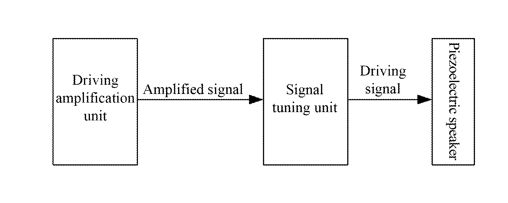
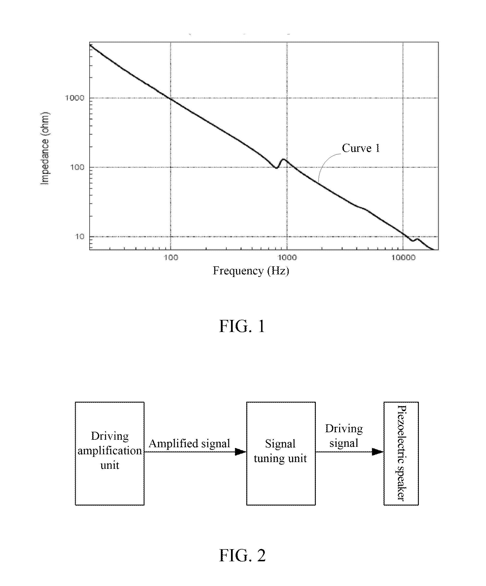
[0026]FIG. 2 is the schematic diagram of the composition structure of the piezoelectric speaker driving device in accordance with an embodiment of the present document; the piezoelectric speaker driving device shown in the FIG. 2 includes the driving amplification unit, the signal tuning unit, and the piezoelectric speaker; thereinto,

[0027]the driving amplification unit is configured to amplify the signal source, and then transmit the amplified signal to the signal tuning unit; the specific implementation of the driving amplification unit belongs to the related art.

[0028]the signal tuning unit is configured to filter the amplified signal for filtering out a high-frequency noise, and regulate the impedance characteristic of the piezoelectric ceramic to increase the load impedance of the high-frequency part of the driving circuit and to reduce the driving current of the high-frequency part of the driving circuit, and transmit the regulated driving signal to the piezoelectric speaker t...


PUM


Abstract

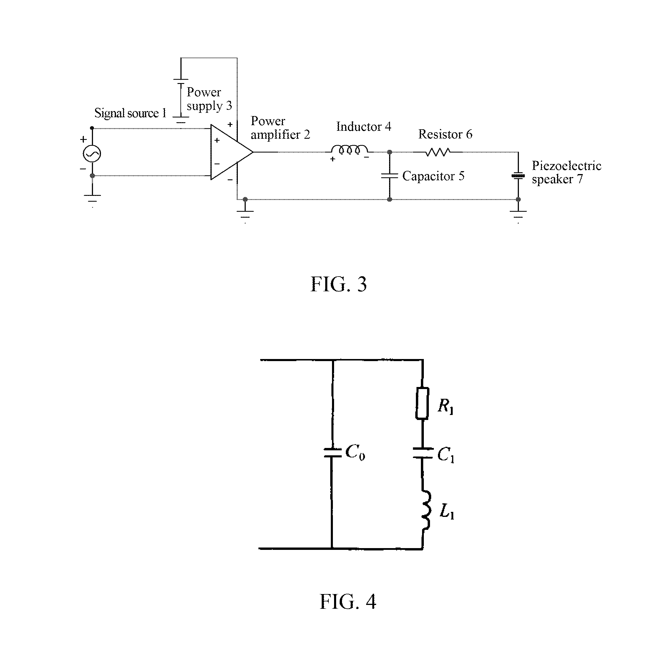
A piezoelectric speaker driving device includes a driving amplification unit, a signal tuning unit, and a piezoelectric speaker; wherein, the driving amplification unit is configured to amplify a signal source, and transmit an amplified signal to the signal tuning unit; the signal tuning unit is configured to filter the amplified signal to filter out a high-frequency noise, and regulate an impedance characteristic of the piezoelectric ceramic to increase a load impedance of a high-frequency part of the driving circuit so as to reduce the driving current of the high-frequency part, and transmit the regulated driving signal to the piezoelectric speaker to drive the piezoelectric speaker. Wherein, the signal tuning unit may include a low-pass filtering circuit and a regulation impedance.

Description

TECHNICAL FIELD[0001]The present document relates to speaker technology, and in particular, to a piezoelectric speaker driving device in an electronic product such as a mobile phone, a tablet PC, etc including a speaker.BACKGROUND OF THE RELATED ART[0002]When a piezoelectric crystal or piezoelectric ceramic is subjected to an external electric field, a mechanical deformation which is in linear relationship with the electric field intensity is generated in the piezoelectric crystal or piezoelectric ceramic. This phenomenon is known as inverse piezoelectric effect. Therefore, when an electric signal is applied on the electric ceramic, the electric ceramic itself may vibrate mechanically correspondingly, and further drive the ambient air to vibrate, so as to generate a sound.[0003]In comparison to traditional moving-coil speakers, the piezoelectric speaker has advantages of compactness, lightweight, impact resistance, low electromagnetic radiation, and low power consumption, etc. Howev...

Claims


Application Information

Patent Timeline
Patent Type & Authority Applications(United States)
IPC IPC(8): H04R3/04H04R3/00H04R17/00
CPCH04R3/04H04R17/005H04R2430/01H04R2430/03H04R3/007H04R17/00
Inventor QIN, SHIJUNYUAN, SHIMINBIAN, XUEHENG
Owner ZTE CORP
Learn More