
Satellite communication system architecture

Inactive Publication Date: 2007-11-15
CHEN CHAO CHUN
View PDF17 Cites 19 Cited by
  • Summary
  • Abstract
  • Description
  • Claims
  • Application Information

AI Technical Summary

Benefits of technology

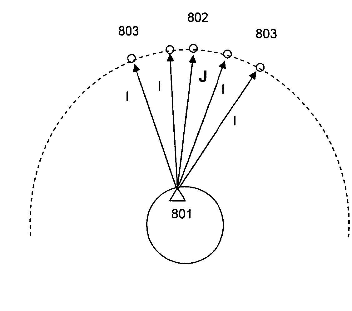
[0024] Embodiments of the present invention may be used to optimize usage of available satellite resources by providing a shared military / non-military satellite communication architecture. Such an architecture may be provided by including in a satellite payload components needed by each portion of the system and components that may be shared among portions of the system. The architecture may also include the use of satellite placement and / or particular deployment strategies in order to reduce a threat of hostile electronic interference and / or physical attacks. Such strategies may be augmented with additional strategies at one or more terrestrial terminals (where “terrestrial” may denote land-, sea-, or air-based terminals, but not space-based terminals).

Problems solved by technology

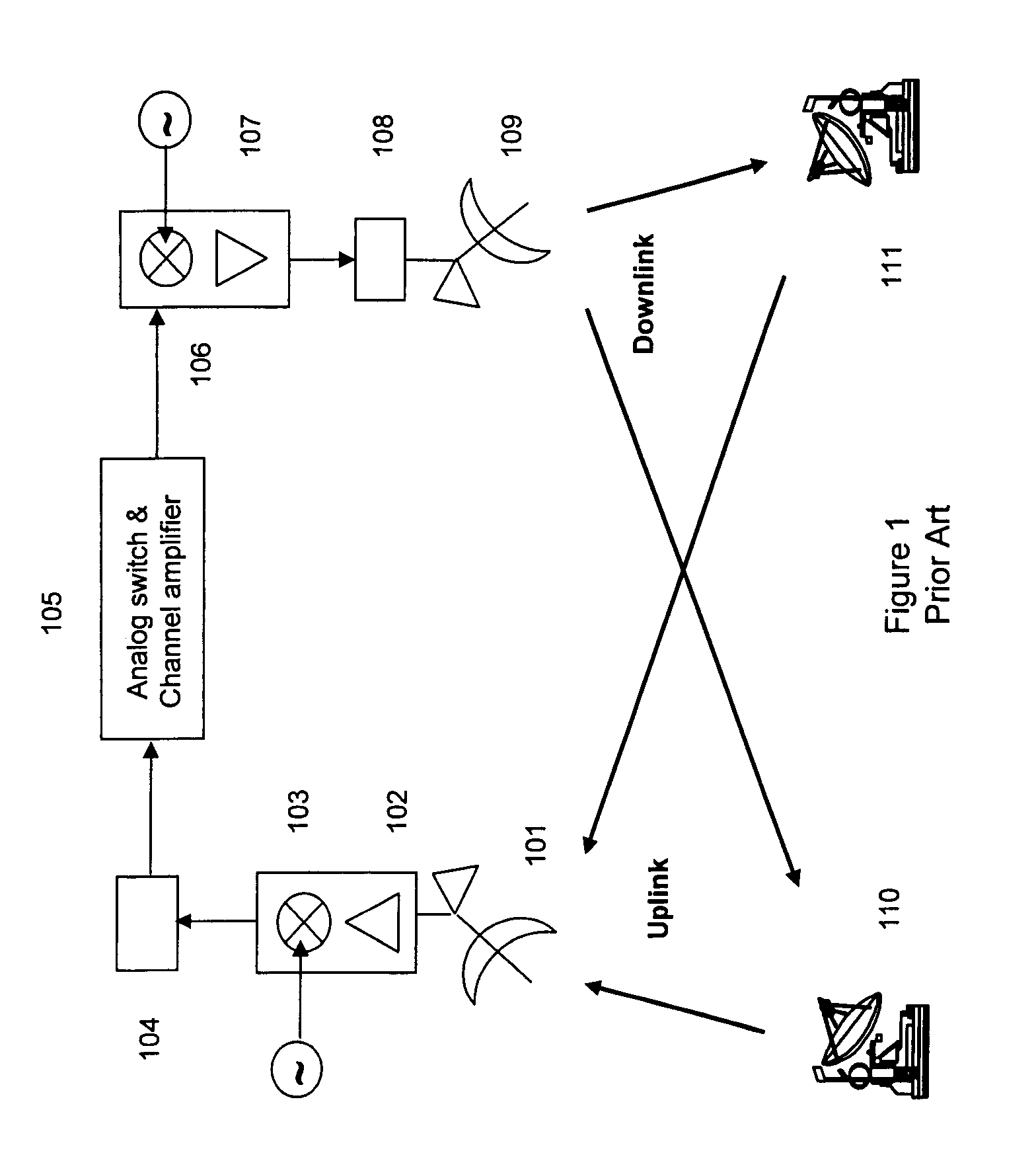
This analog repeater (or bent-pipe transponder) architecture is vulnerable to uplink interference.
It can be easily disrupted by intentional interference, as well as by unintentional interference because there is no onboard signal processing capability to remove or suppress the interference.
If the uplink interference signal is stronger than the desired signal, the interference signal may dominate the satellite amplification power and result in an extremely corrupted output signal.
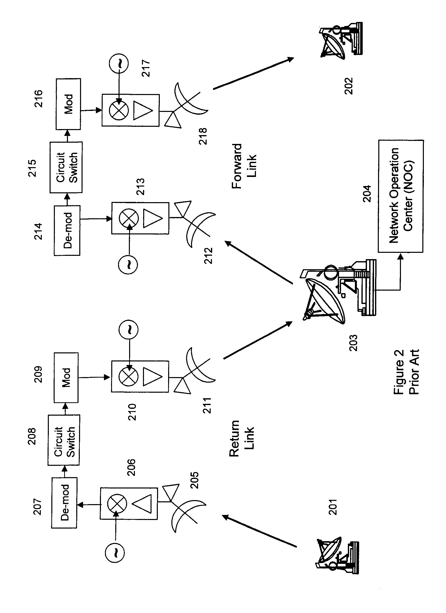
While the double-hop bent-pipe architecture may result in increased network coverage, it is still subject to the same type of interference problems that are encountered in the single-hop bent-pipe architecture.
Additionally, the use of a second hop and intermediate signal processing introduces further delays, which may negatively impact, for example, voice communications.
However, this resistance to interference comes at the expense of complexity and cost.
Additionally, problems arise due to limited availability of resources.
Furthermore, orbital locations for satellites are becoming less and less available as the standard orbits become more and more congested with satellites; this may lead to mutual interference between communication signals to and from satellites located close to each other.

Method used


Image

  • Satellite communication system architecture
  • Satellite communication system architecture
  • Satellite communication system architecture

Examples


Embodiment Construction

[0031] Exemplary embodiments of the invention are discussed in detail below. While specific exemplary embodiments are discussed, it should be understood that this is done for illustration purposes only. A person skilled in the relevant art will recognize that other components and configurations can be used without parting from the spirit and scope of the invention.

[0032]FIG. 5 depicts an exemplary embodiment of the present invention. In FIG. 5, both military users 501, 504 and non-military users 502, 503 may share common resources of a single satellite processing system 505-517. In particular, the system of FIG. 5 may have military users, e.g., 501, transmitting using SS signaling, which may be FH signaling, as discussed above, and the uplink SS signals may be received at the satellite by an antenna 505, which may, for example, include a beam-forming network (BFN) and / or be gimbaled. A BFN may be used to provide multiple uplink channels (and to create associated channel separation ...


PUM


Abstract

A satellite communication system architecture that supports both commercial and tactical applications may include polarization-based and / or frequency-based multiplexing and de-multiplexing and common routing. Such a satellite communication system may be implemented in such a way as to minimize intentional interference.

Description

CROSS-REFERENCE TO RELATED APPLICATION [0001] This application is a continuation-in-part of U.S. patent application Ser. No. 11 / 216,110, filed on Sep. 1, 2005, which claims the priority of U.S. Provisional Patent Application No. 60 / 637,308, filed on Dec. 18, 2004, both of which are incorporated herein by reference.BACKGROUND OF THE INVENTION [0002] 1. Field of the Invention [0003] This invention generally relates to communication systems. Specific embodiments of the invention relate to satellite-based communication systems, which may use one type of waveform for transmitting tactical / military user signals and a second type of waveform for transmitting commercial / non-military user signals. Tactical user signals and commercial signals may be digitally processed separately and passed to a common router to enable connection of tactical users to commercial users, or vice versa, without relaying to the ground for processing and routing. [0004] 2. Related Art [0005] Satellite-based communi...

Claims


Application Information

Patent Timeline
IPC IPC(8): H04K3/00
CPCH04B7/18515
Inventor CHEN, CHAO-CHUN
Owner CHEN CHAO CHUN
Learn More