Optimized Placement Of Product On Flat-Line Conveyor

Inactive Publication Date: 2021-01-07
HERMANCE MACHINE
View PDF0 Cites 0 Cited by
  • Summary
  • Abstract
  • Description
  • Claims
  • Application Information

AI Technical Summary

Benefits of technology

[0005]The limitations of the prior art are addressed by the present invention, which relates to an industrial system requiring the use of a flat-line conveyor and, more particu

Problems solved by technology

Inevitably, this technique yields problems in terms of efficiency, uniformity, and quality of the results.
For example, in the case of applying a layer of spray paint, if the parts are too far apart, a significant amount of the paint is inevitably wasted by spraying vacant locations on the belt.
On the other hand, if the parts are placed too close together on the

Method used


Image

  • Optimized Placement Of Product On Flat-Line Conveyor
  • Optimized Placement Of Product On Flat-Line Conveyor
  • Optimized Placement Of Product On Flat-Line Conveyor

Examples


Example

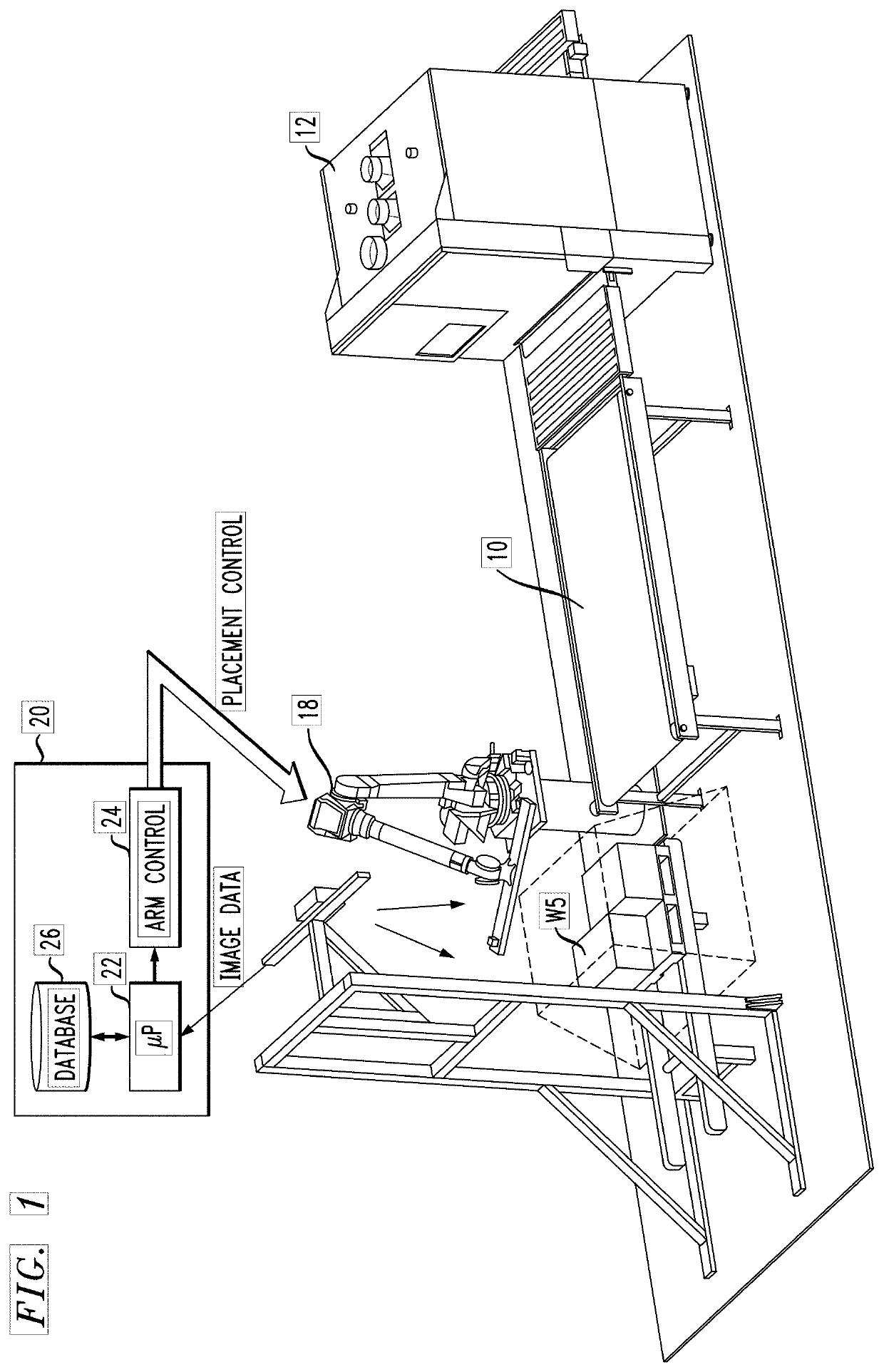
[0018]FIG. 1 is a simplified block diagram of an exemplary system utilizing the automated conveyor belt placement apparatus and method of the present invention. Shown in particular is a conventional conveyor belt 10 that is used to introduce product into an apparatus 12 used to perform a particular function. For example, as mentioned above, apparatus 12 may comprise a sanding tool, with conveyor belt 10 used to introduce various, random pieces of wood to apparatus 12. It is presumed for the purposes of the present invention that the pieces of wood are flat and are of varying surface area sizes.

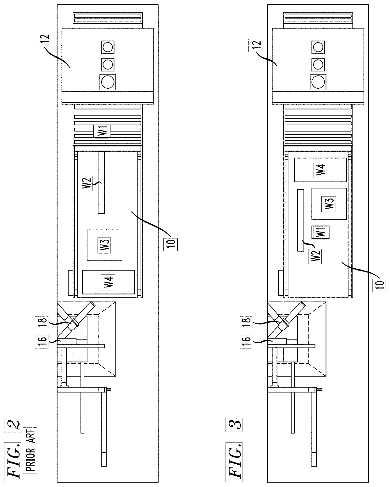
[0019]FIG. 2 is a top view of conveyor belt 10 and apparatus 12, showing a typical prior art method of placing product on belt 10. Here, each successive piece of wood to be sanded (denoted as W1, W2, W3 and W4 for the sake of explanation) is placed in a central region of conveyor belt 10 and passed through sanding apparatus 12. Even if mechanized apparatus is used to “pick and place” the piece...


PUM


Abstract

A computer-controlled system of placing product on a conveyor belt entrance to an industrial tool is based upon the combination of a 3D vision system (used to capture image data defining the surface area of a “next” product(s) to be placed) and a processor that is configured to determine an optimum location for placing that “next” product(s) on the conveyor belt. The processor then instructs a robotic arm to pick up and place the product at the processor-defined optimum location. Depending on the specific task to be performed by the industrial tool, the detailed analysis used to determine the optimum location will differ.

Description

CROSS-REFERENCE TO RELATED APPLICATIONS[0001]This application claims the benefit of U.S. Provisional Application No. 62 / 869,756, filed Jul. 2, 2019 and herein incorporated by reference.TECHNICAL FIELD[0002]The present invention relates to an industrial system requiring the use of a flat-line conveyor and, more particularly, to a robot-controlled pick-and-place system for efficiently loading product onto the conveyor belt in a manner that optimizes usage of the specific industrial system.BACKGROUND OF THE INVENTION[0003]There are a variety of different industrial processes that utilize a flat-line conveyor belt to move product through a machine that performs one or more operations on the product. For example, metallic components of an assembly that require painting (staining / coating) may be placed on a conveyor belt and moved through an enclosed spraying apparatus. Wood products that require sanding may be placed on a conveyor belt and passed underneath a wide belt sanding apparatus....

Claims


Application Information

Patent Timeline
IPC IPC(8): B25J9/16B25J9/00B23Q7/04
CPCB25J9/1697B25J9/0093B23Q7/048B25J9/1669B25J9/0084B25J9/163G05B2219/37567G05B2219/39102G05B2219/39553G05B2219/45013
Inventor STROUSE, IANDEMOTTE, DONALDSPIVEY, JURELLGOLDER, BRADLEY G.
Owner HERMANCE MACHINE
Why Eureka
Try Eureka