Pruning clipper

a clipper and clipping technology, applied in metal-working hand tools, horticulture, agricultural tools and machines, etc., can solve the problem of high manufacturing cos

Inactive Publication Date: 2007-11-22
LIN THOMAS
View PDF13 Cites 26 Cited by
  • Summary
  • Abstract
  • Description
  • Claims
  • Application Information

AI Technical Summary

Benefits of technology

[0005]The present invention has been accomplished under the circumstances in view. It is therefore an objective of the present invention to provide a pruning clipper, which allows adjustment of the open angle of the cutting mouth.

Problems solved by technology

This design of cutting mouth adjustable pruning clipper is functional; however, the rail and the slidable push button have a complicated structure, resulting in a high manufacturing cost.

Method used


Image

  • Pruning clipper
  • Pruning clipper
  • Pruning clipper

Examples


Embodiment Construction

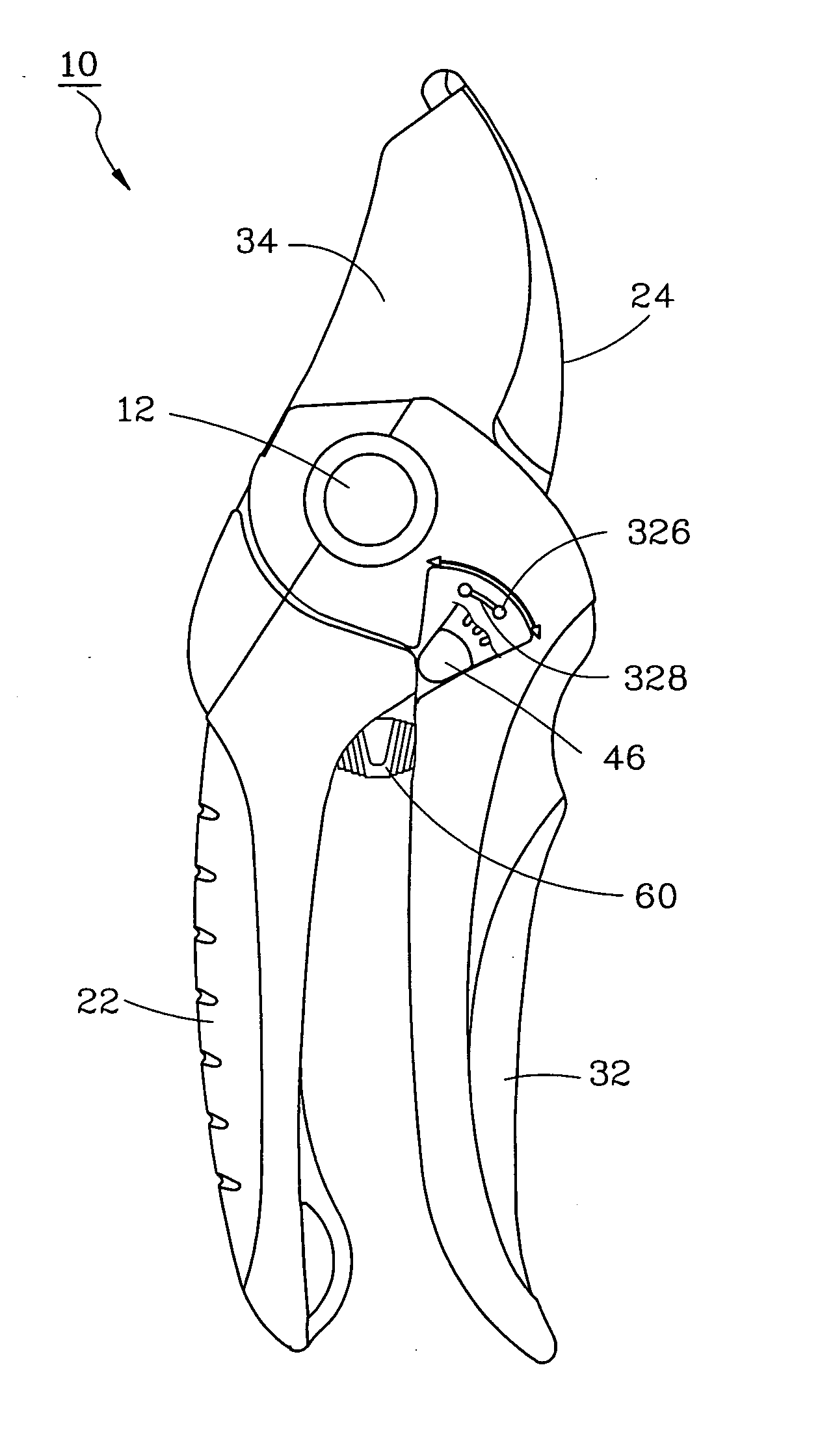
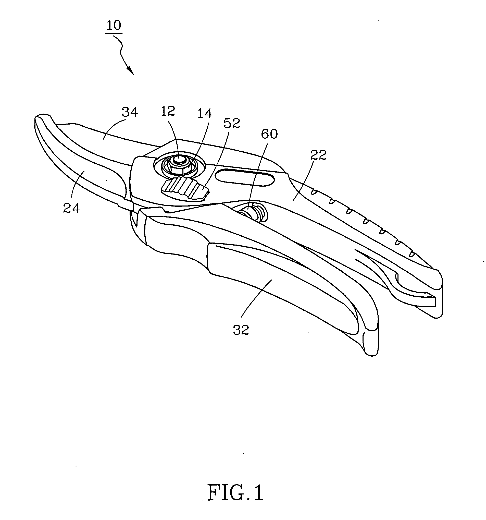
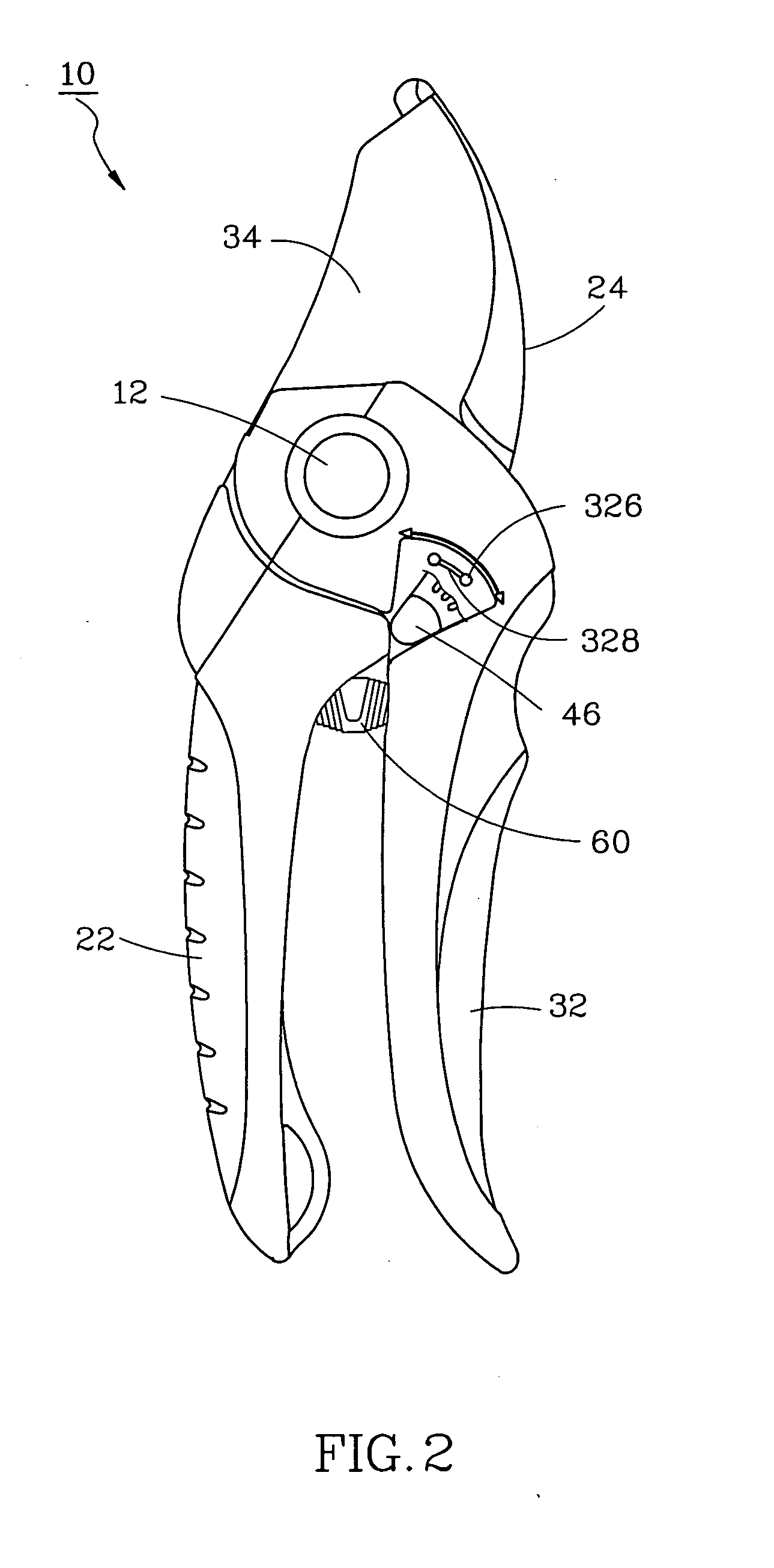
[0019]As shown in FIGS. 1-3, a pruning clipper 10 in accordance with a preferred embodiment of the present invention comprises of a first clipper member 20, a second clipper member 30, a first adjustment member 40, a second adjustment member 50, and a spring member 60.

[0020]The first clipper member 20 has a grip 22 and a blade 24 mounted on one end of the grip 22. The blade 24 has a stop edge 242 adjacent to the end edge of the grip 22, and a positioning groove 244.

[0021]The second clipper member 30 is pivotally coupled to the first clipper member 20 with a screw bolt 12 and a nut 14. The second clipper has a grip 32 and a blade 34 mounted on end of the grip 32. The grip 32 has a circular through hole 322, a stop edge 324 adjacent to the blade 34, two recessed holes 326 on the outer side thereof, and a guide groove 328 connected between the two recessed holes 326. The blade 34 has a positioning groove 342, which has an open end 324a and a close end 342b. The width of the positioning...


PUM


Abstract

A pruning clipper includes a first clipper member having a stop edge, a second clipper member pivoted to the first clipper member and provided with a through hole, and a first adjustment member having a pivot pin pivotally inserted into the through hole of the second clipper member, and a stop rod connected to the pivot pin and turnable with the pivot pin between a first position where the stop rod is disengaged with the stop edge of the first clipper member and a second position where the stop rod is stopped at the stop edge of the first clipper member to limit the open angle between the first and second clipper members.

Description

BACKGROUND OF THE INVENTION[0001]1. Field of the Invention[0002]The present invention relates to a pruning clipper and more particularly, to a simple structure of pruning clipper, which allows adjustment of the open angle of the cutting mouth.[0003]2. Description of the Related Art[0004]Taiwan Patent Publication No. 00365110 discloses a cutting mouth adjustable pruning clipper. According to this design, the pruning clipper comprises a first blade, a second blade, a first grip, a second grip, a slidable push button, and a spring member. The first blade has a retaining groove. The first blade and the second blade define a cutting mouth. The slidable push button is slidably coupled to a rail at the second grip. The spring member supports the first blade and the second blade to open the cutting mouth. When the user operates the pruning clipper to open the cutting mouth after the user has pushed the slidable push button to the topmost end of the rail, the slidable push button will be for...

Claims


Application Information

Patent Timeline
Patent Type & Authority Applications(United States)
IPC IPC(8): B25F3/00B26B1/00
CPCA01G3/021A01G3/02
Inventor LIN, THOMAS
Owner LIN THOMAS
Why Eureka
Try Eureka