
System for Digital Writing

Inactive Publication Date: 2007-11-22
KONINK KPN NV
View PDF1 Cites 1 Cited by
  • Summary
  • Abstract
  • Description
  • Claims
  • Application Information

AI Technical Summary

Benefits of technology

[0010] According to one aspect of the invention a digital writing system for providing handwritten information to a computer system application is disclosed. The digital writing system can comprise an electronic display and a digital writing and scanning device capable of detecting its position based on a position-coding pattern. This position-coding pattern is superimposed on the surface of the electronic display. The digital writing system according to the invention can be implemented in a desktop PC system, but also in laptop, notebook, palmtop, a tablet PC or any other computing system. Also a small device like a PDA can be used to implement the system. The digital writing and scanning device can have the form of a digital pen, but can also have any other form convenient for the user and the application. The scanning device could be a pen like device that has a camera inside to read the code. Furthermore a source of light can be included to light up the surface of the screen. The used light need not be in the visual range. Preferably not, since this might disturb the readability of the screen. The electronic display device can be of any type, including but not limited to TFT, LCD, Television, OLED etc. Superimposing the location-coding pattern on the electronic display has the advantage that the display can be used as input means for the computer without the need to physically adapt the screen. Another advantage is that the pattern can be used for different kinds of application without the need to develop dedicated paper forms. Because there is no ink applied to the pattern the pattern remains reusable for the next application. The location-coding pattern that is superimposed on the surface of the display device can exist of a pattern of small marks. The marks form a unique grid over the total surface of the screen. These marks can be applied to the screen with printing techniques or any other means differentiating small parts of the surface. The difference between the surface and the marks can e.g. exist in differences in colour, brightness, reflectivity etc. Preferably the marks are not visible with the human eye. This has the advantage that the vision of the screen is not deteriorated. The code can also be placed on a more or less transparent sheet that can be applied to the electronic display device. This has the advantage that the system can be used without any adaptations to an existing display device.

Problems solved by technology

Preferably not, since this might disturb the readability of the screen.

Method used


Image

  • System for Digital Writing
  • System for Digital Writing

Examples


Embodiment Construction

[0014] For the purpose of teaching of the invention, preferred embodiments of the method and system of the invention are described in the sequel. It will be apparent to the person skilled in the art that other alternative and equivalent embodiments of the invention can be conceived and reduced to practice without departing from the true spirit of the invention, the scope of the invention being only limited by the claims as finally granted.

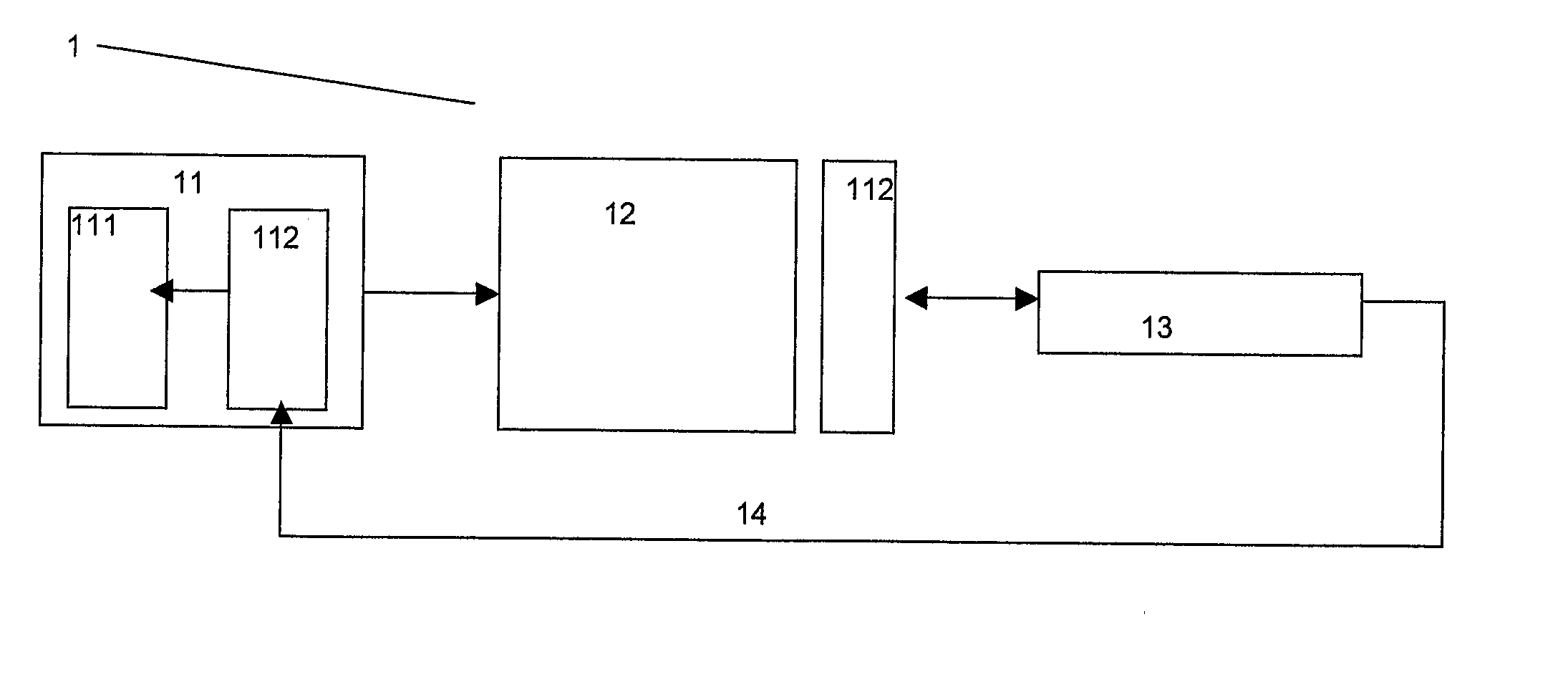
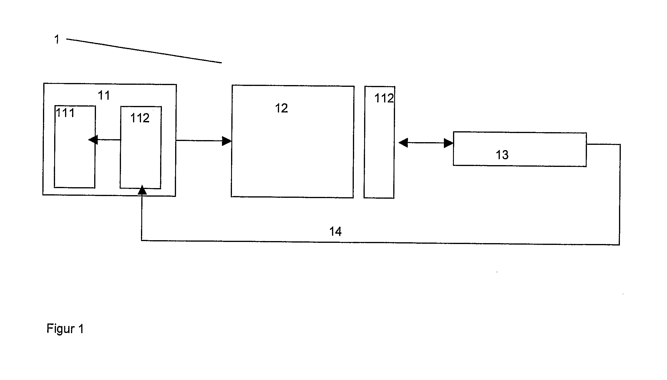
[0015] The digital writing system (1) according to an embodiment of the invention comprises a CPU (11) an electronic display device (12) and an electronic writing and scanning device (13). The system according to the invention can also comprise other elements, e.g. a keyboard and a printer, but these elements are less relevant for explaining the invention and therefore not depicted in FIG. 1.

[0016] This embodiment of the invention is implemented in a desktop PC like configuration but could also be implemented in another system or device. On the C...


PUM


Abstract

A digital writing system for providing handwritten information to a computer system application is disclosed. The digital writing system can comprise an electronic display and a digital writing and scanning device capable of detecting its position based on a position-coding pattern. This position-coding pattern is superimposed on the surface of the electronic display.

Description

FIELD OF THE INVENTION [0001] The present invention is related to communication systems. More specifically, a system for digital writing is disclosed. BACKGROUND OF THE INVENTION [0002] Since several years digital writing systems are available on the market. These systems usually comprise a dedicated pen including a normal ink pen, a camera and a means of communicating with external devices, e.g. via Bluetooth. The pen is used to write on a special piece of paper, which contains a unique specific pattern of small dots, a so-called position-coding pattern. Some available systems are based on technology developed by Anoto AB from Sweden. This technology is disclosed in a number of patents, e.g. WO0126032A1. The position-coding pattern can be printed on a variety of general or specially developed paper products, e.g. note blocks or forms. [0003] With this combination of pen, paper and communication means a wide range of applications can be developed. These applications can include hand...

Claims


Application Information

Patent Timeline
IPC IPC(8): G06F17/00
CPCG06F1/1601G06F3/04883G06F3/03545
Inventor HARTMANN, FRANCISCUS KOENRAAD DIEDERIK MARIA
Owner KONINK KPN NV
Learn More