Histogram adjustment for high dynamic range image mapping

Inactive Publication Date: 2007-11-22
XEROX CORP
View PDF10 Cites 87 Cited by
  • Summary
  • Abstract
  • Description
  • Claims
  • Application Information

AI Technical Summary

Problems solved by technology

These devices are not able to directly reproduce high dynamic range images (usually 12, 16, or even 32 bits per channel).
If the same quantization step is used to convert from high to low dynamic range, then either the brightest part of the image or the darkest part of the image is often lost.
However, most of these techniques are unable to reprodu

Method used


Image

  • Histogram adjustment for high dynamic range image mapping
  • Histogram adjustment for high dynamic range image mapping
  • Histogram adjustment for high dynamic range image mapping

Examples


Embodiment Construction

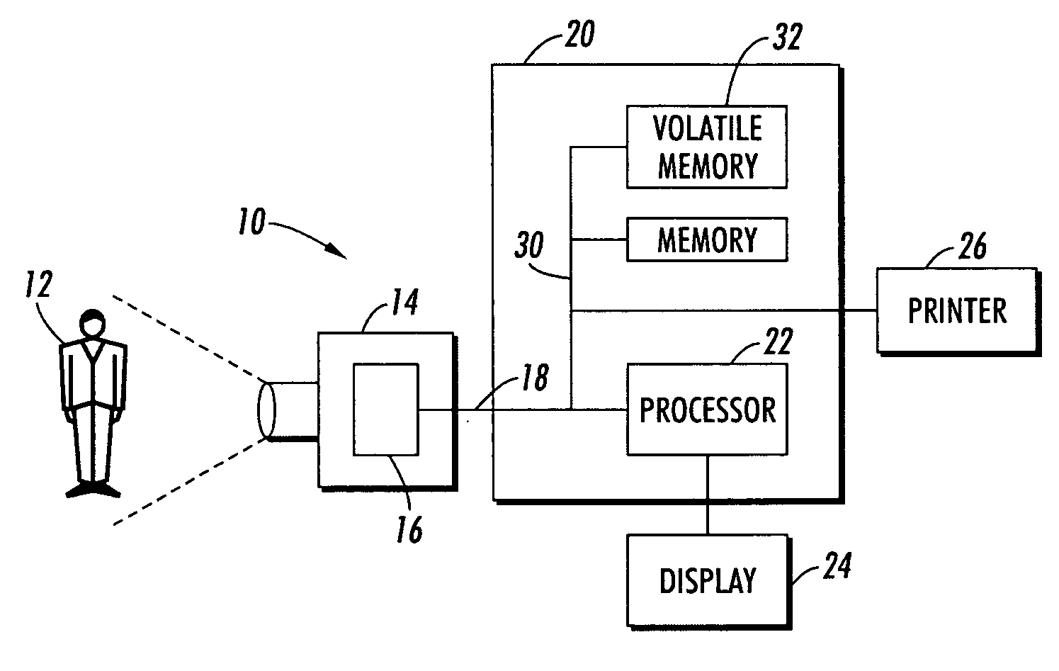
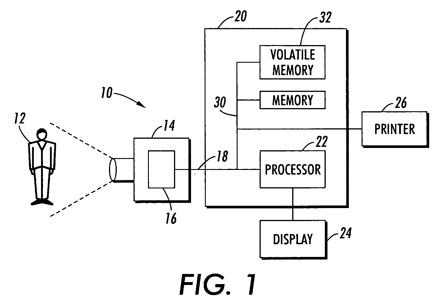
[0020]The exemplary embodiment relates to a system and method for compression of high dynamic range images to images with a lower dynamic range which retains a pleasing and realistic appearance of high dynamic range scenery when rendered on low dynamic range devices.

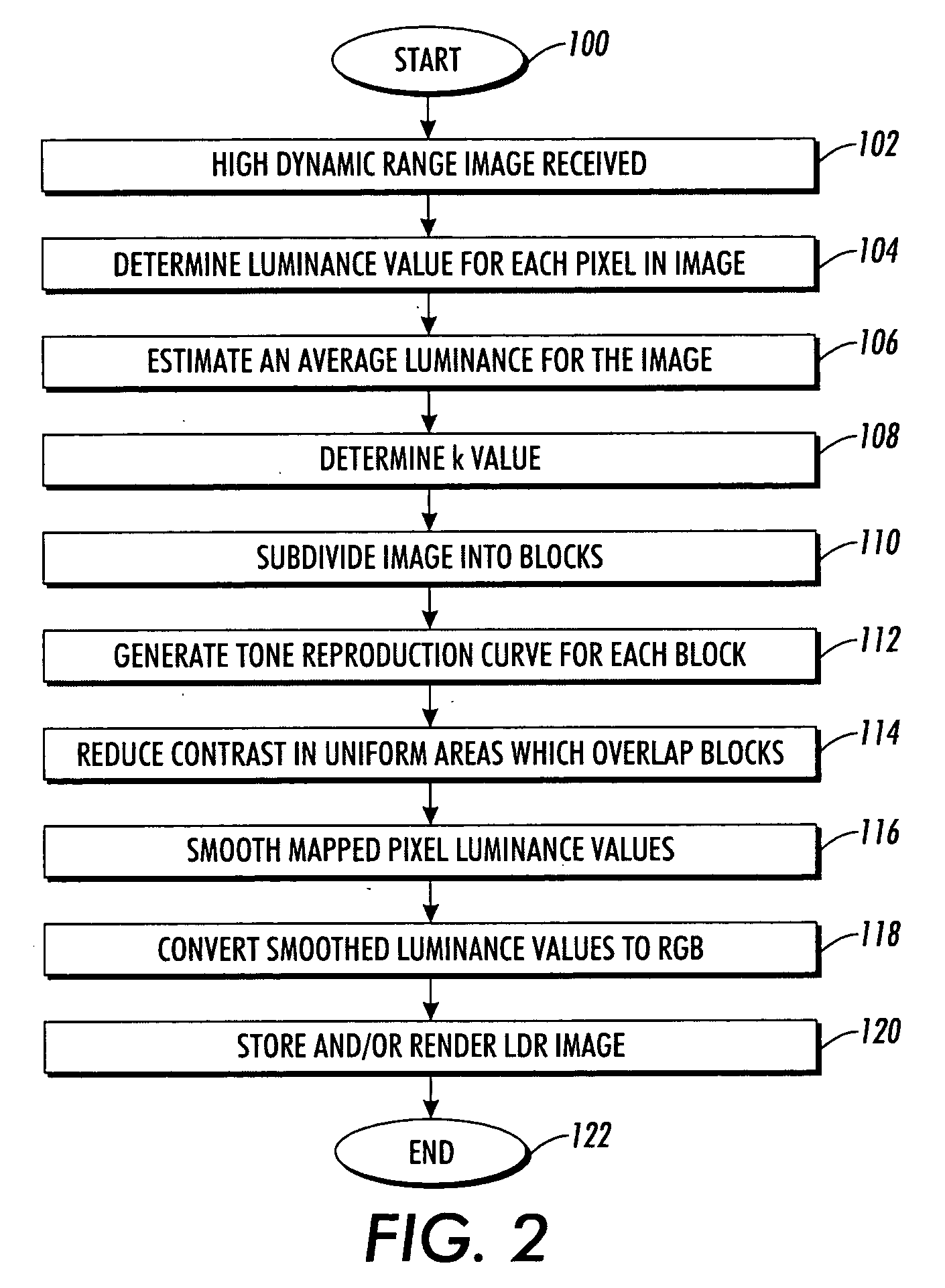
[0021]The technique is suited to use in a fully automated, fast tone reproduction method that reproduces local contrast and fine details of the sceneries without introducing artifacts.

[0022]In various aspects, the method includes automatically setting the overall brightness (luminance) of the mapped high dynamic range image in an initial logarithmic dynamic range compression. In various aspects, local histograms are adjusted to reproduce the local contrast and details of high dynamic range image based on a windowed application approach. Noise artifacts may be avoided or reduced by controlling the degree of contrast enhancement in different windows according to the relative uniformity inside the window. The method is able...


PUM


Abstract

A method of automatic mapping of image data includes representing image data for an image as luminance values, determining a key value as a function of an average luminance value of the image and of minimum and maximum luminance values of the image, generating offset-adjusted luminance values including applying an offset to each of the luminance values, the offset being a function of the determined key value, and computing a tone reproduction curve for at least a region of the image which includes applying a mapping function to the offset-adjusted luminance values.

Description

CROSS REFERENCE TO RELATED PATENTS AND APPLICATIONS[0001]Application Ser. No. 11 / 174,679 (Attorney Docket No. 20041050-US-NP), filed Jul. 5, 2005, entitled “Contrast Enhancement of Images,” by Christopher Dance, et al., the disclosure of which is incorporated herein in its entirety by reference, is mentioned.BACKGROUND[0002]The exemplary embodiment relates to image processing. It finds particular application in connection with the mapping of images from a higher to a lower dynamic range.[0003]The “dynamic range” of a scene, image, or a reproduction device is defined as the ratio between the highest and lowest luminance levels. Recent technologies have made it relatively easy to create radiance maps for High Dynamic Range (HDR) sceneries. Conventional low dynamic range (LDR) reproduction devices, such as printers and CRT monitors, are typically 8-bit, i.e., the luminance can range in integer values from 0 to 255. These devices are not able to directly reproduce high dynamic range ima...

Claims


Application Information

Patent Timeline
IPC IPC(8): G06K9/40
CPCG06T5/007G06T5/40H04N5/20G06T2207/20208G06T2207/20012H04N1/4074H04N9/64H04N5/57
Inventor DUAN, JIANGBRESSAN, MARCODANCE, CHRISTOPHER R.QIU, GUOPING
Owner XEROX CORP
Why Eureka
Try Eureka