Graft fixation implant

a technology for fixing implants and ligaments, applied in the field of graft fixation implants, can solve problems such as difficult repositioning or removal of devices

Active Publication Date: 2007-11-22
LINVATEC
View PDF36 Cites 96 Cited by
  • Summary
  • Abstract
  • Description
  • Claims
  • Application Information

AI Technical Summary

Benefits of technology

[0007]These and other objects are achieved by a preferred embodiment disclosed herein which is a graft fixation implant comprising an elongated body having a proximal end, a distal end, a central portion interposed between the proximal and distal ends, a longitudinal axis extending through the proximal and distal ends and a transverse axis extending through the central portion. The body has an axially aligned proximal aperture in the proximal end and an axially aligned distal aperture in the distal end. Both apertures extend through the body and are within a common plane which includes the longitudinal axis. A pulling-suture receiving aperture extends through the central portion and is aligned parallel to the common plane and spaced laterally from the longitudinal axis. A pulling-suture threaded through the pulling-suture receiving aperture and pulled distally will create a turning moment in the implant.

Problems solved by technology

Furthermore, such devices are not easily repositioned or removed once set in place.

Method used


Image

  • Graft fixation implant
  • Graft fixation implant
  • Graft fixation implant

Examples


Embodiment Construction

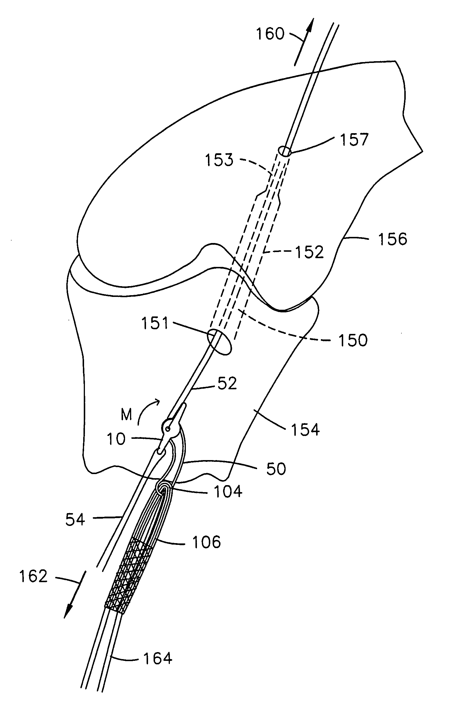
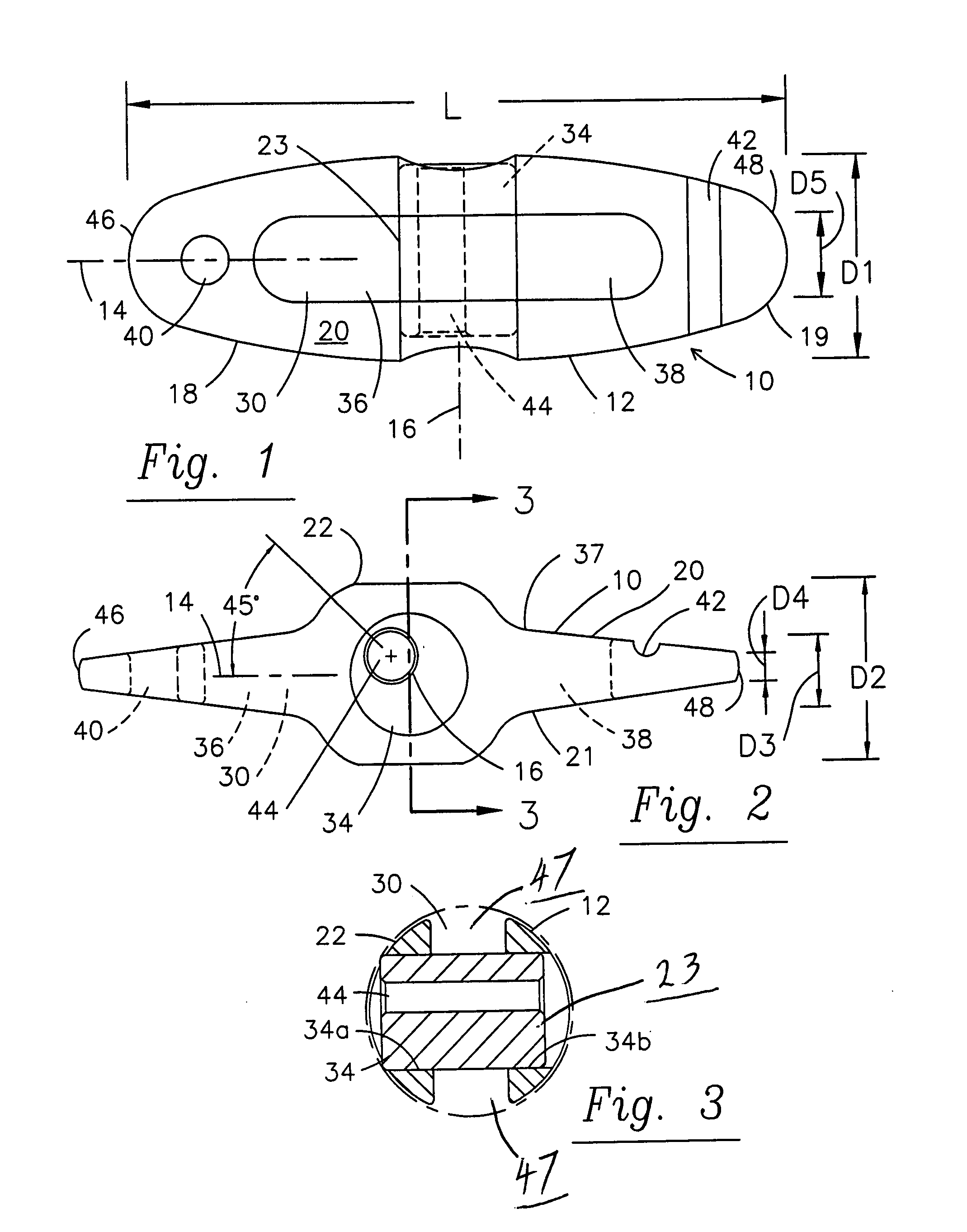
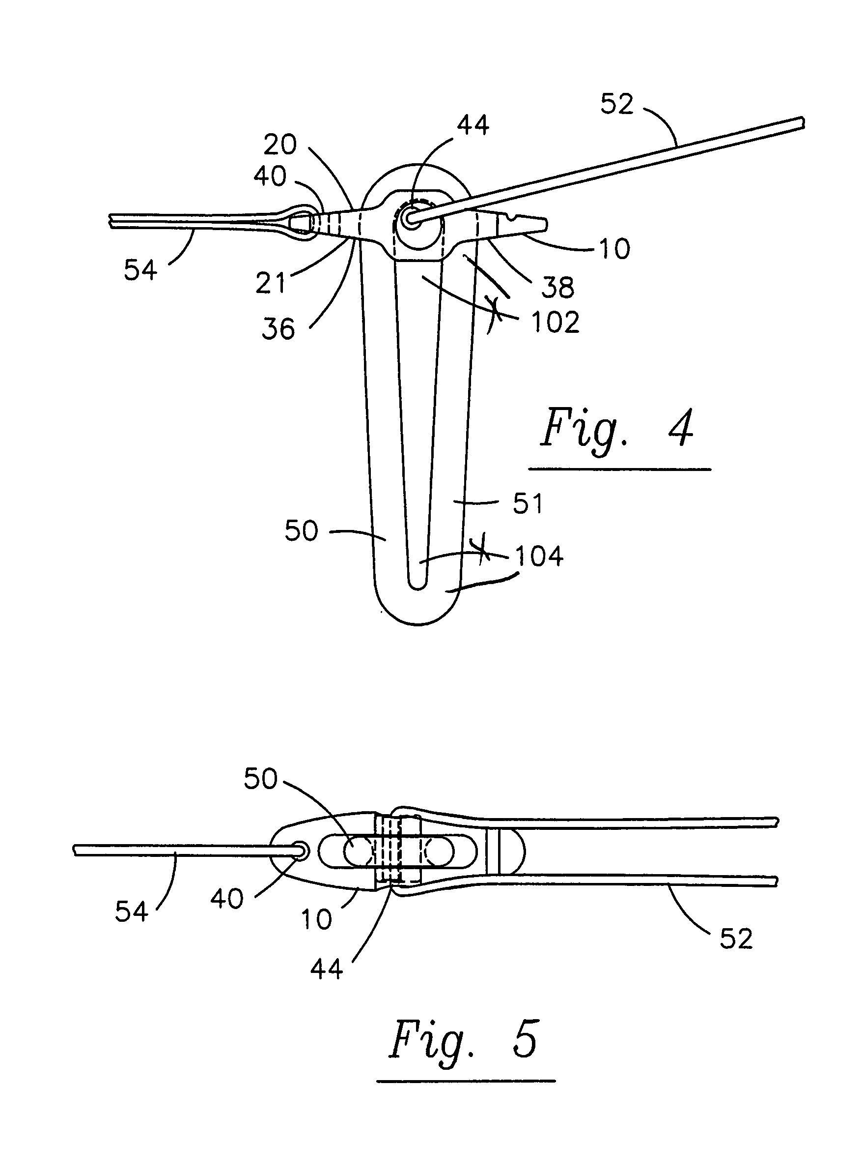
[0039]FIG. 1 is a top plan view of a preferred embodiment of a graft fixation implant 10 constructed in accordance with the principles of this invention. The terms “graft fixation implant” and “ligament anchor” and “anchor” may be used interchangeably herein. Ligament anchor 10 comprises a generally elliptical body 12 (when viewed in a top plan view), formed from biocompatible, absorbable or non-absorbable materials having a longitudinal axis 14, a transverse axis 16 and proximal and distal ends 18 and 19. Body 12 lies generally in the plane of the paper showing FIG. 1. The proximal end 18 is that portion of body 12 from axis 16 to the left in FIG. 1. Similarly, the portion to the right is distal end 19. The profile in this top plan view may be rectilinear or more rectilinear and less elliptical for certain applications.

[0040]As best seen in FIGS. 1 and 2, anchor 10 also has top and bottom surfaces 20 and 21, respectively, and a central body portion 22 interposed between ends 18 and...


PUM


Abstract

The subject invention is a fixation device or anchor intended to secure a graft ligament or other soft tissue repair. The device is designed to be attached to a graft ligament and to secure the graft within a bone tunnel by extending transversely across the opening of the tunnel. In certain procedures the device is intended to pass through a bone tunnel in an orientation generally aligned with the tunnel and then turn transversely. The device has an inherent tendency to rotate upon exiting the tunnel to thereby become automatically transversely aligned with the tunnel and the graft ligament. The rotation is due to a moment automatically created as a resultant of forces applied to the anchor by a pulling-suture via a laterally offset aperture joining the pulling-suture to the anchor.

Description

[0001]The present application is related to and claims the benefit under 35 USC 119(e) of U.S. Provisional Applications Ser. No. 60 / 801314 filed May 18, 2006 and Ser. No. 60 / 855853 filed Nov. 1, 2006.FIELD OF THE INVENTION[0002]The invention relates generally to devices and procedures for securing artificial graft ligaments within bone tunnels. More particularly, the invention relates to devices and procedures for securing graft ligaments in the repair of the anterior cruciate ligaments and posterior cruciate ligaments of the knee.BACKGROUND OF THE INVENTION[0003]Due to the frequency of injury to various ligaments such as the anterior cruciate ligament (ACL), especially in sports, and similar injury to other ligaments and related structures, there is a great deal of prior art dealing with a replacement of these structures with ligament grafts. Much of this prior art is concerned with ensuring proper placement of bone tunnels drilled in the bones intended to receive the opposed ends ...

Claims


Application Information

Patent Timeline
Patent Type & Authority Applications(United States)
IPC IPC(8): A61B17/58
CPCA61B17/0401A61B2017/0417A61B2017/0414A61B2017/0409
Inventor LOMBARDO, GIUSEPPEBROWN, JESSICASHERMAN, P. ERCELLKAM, ANDREW
Owner LINVATEC
Why Eureka
Try Eureka