Method and Device for Redundancy Control of Electrical Devices

a technology for electrical devices and redundancy control, applied in process and machine control, data switching networks, instruments, etc., can solve the problems of affecting the whole operation, affecting the operation, and a large risk of a split brain scenario, so as to reduce the risk of a split brain, ensure maximum availability and operation safety, and simple and efficient

Inactive Publication Date: 2007-11-22
NOKIA SIEMENS NETWORKS GMBH & CO KG
View PDF8 Cites 13 Cited by
  • Summary
  • Abstract
  • Description
  • Claims
  • Application Information

AI Technical Summary

Benefits of technology

[0012] The advantage inherent in the invention is the provision of a simple and efficient redundancy mechanism that does not require any additional hardware for redundancy control and at the same time guarantees maximum availability and operational safety. This is achieved by providing a two-step redundancy control, the first step (control 1) having at its disposal a neutral third channel which decides which standby circuit to switch to within a redundancy pair (redundancy unit). This concept considerably reduces the risk of split brain. Here the controlling pair is also the controlled pair at the same time. There is therefore no separate mechanism for the controller's switchover to standby, which makes redundancy control conceivably simple and efficient. All the platforms of the redundancy control unit can be loaded with applications that require a redundancy control, meaning that no additional hardware is required. One and the same method means that both the controlling and the controlled unit have high availability.
[0013] Furthermore, a second step (control 2), which describes the control within a redundancy unit is optionally provided. It can be provided in addition to the first step. The combination of both steps has the advantage of a particularly robust redundancy configuration that can even survive multiple failures of electrical devices within the quadruple. In practice, this means that, whenever there is a still a functional platform for a function capable of switching over to standby, this platform redirects the dedicated services.
[0014] It is equally advantageous that this does not result in any negative repercussions on the system. Thus simple handling ensues when the moving the system up from the controlling to the controlled unit. For this purpose, it is possible to move the platforms up in any sequence. The system is capable of operation as soon as the first platform is “act”. In any combination of platforms that are capable of being functional and have failed, the system is the state of maximum redundancy and maximum availability.

Problems solved by technology

Such systems are very expensive, however.
This method involves a relatively large risk of a “split-brain” scenario occurring.
The effects of such a scenario can cause havoc with the whole operation.
This again results in the (expensive) configuration mentioned in the introduction.
Basically, the prior art can be described as expensive or unreliable (sometimes even both).

Method used


Image

  • Method and Device for Redundancy Control of Electrical Devices
  • Method and Device for Redundancy Control of Electrical Devices
  • Method and Device for Redundancy Control of Electrical Devices

Examples


Embodiment Construction

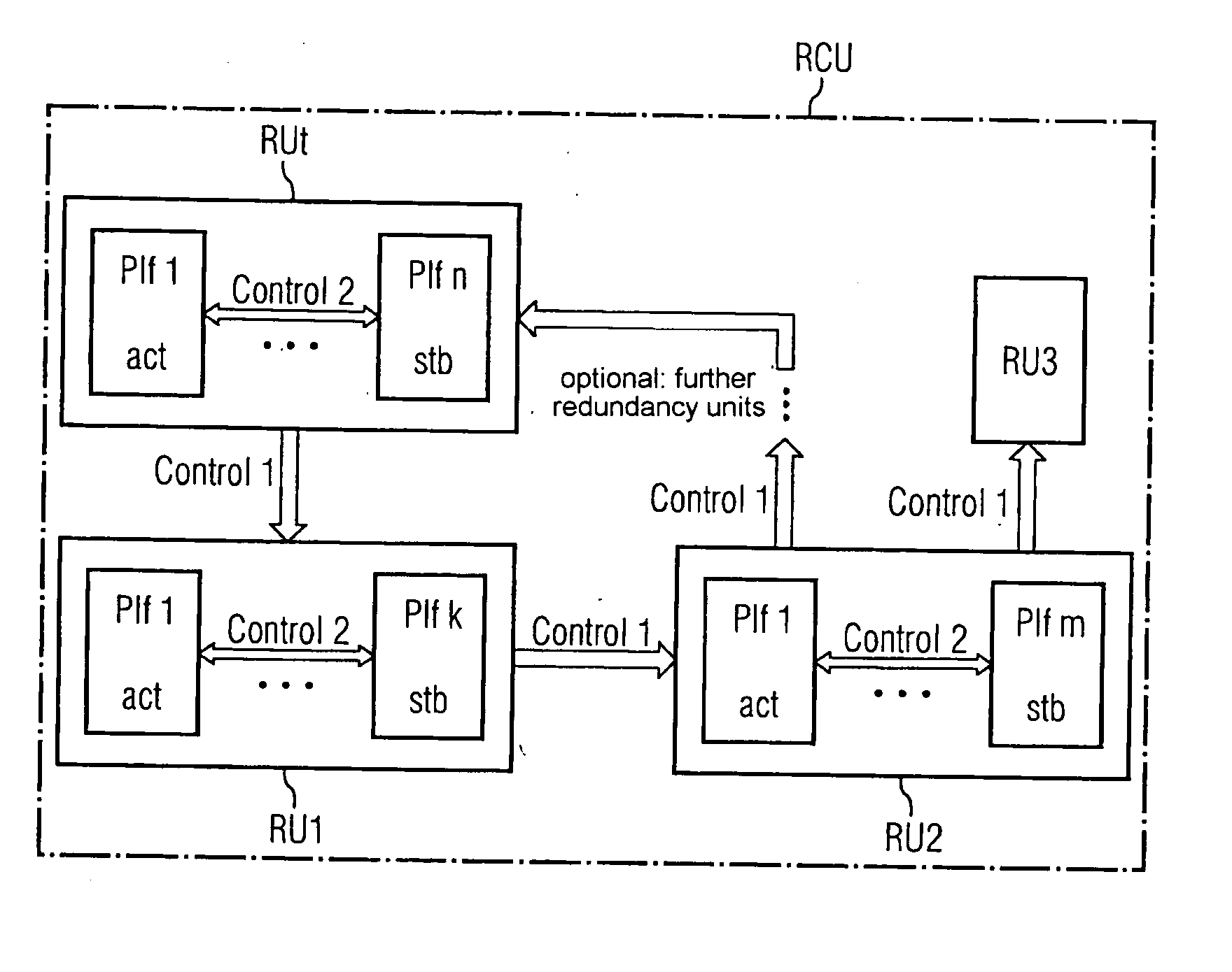
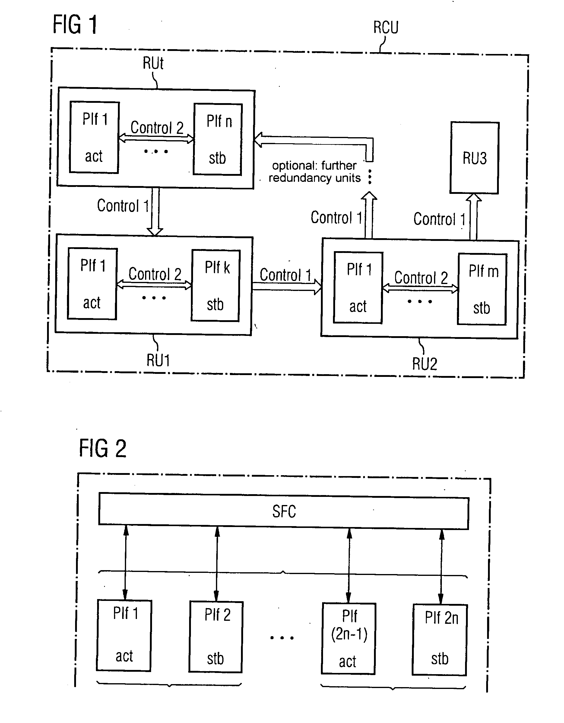
[0022]FIG. 1 shows a redundancy control unit RCU (redundancy control unit) with, for example, four redundancy units RU1, RU2, RU3, RUt. Here a redundancy unit comprises a plurality of electrical devices, which are configured in the present exemplary embodiment as HW / SW platforms. Each redundancy unit may have a number k, l, m, n of platforms that differs from the other redundancy units. The platforms have the feature that each function / application running on a platform of the redundancy unit can be taken over by each other platform of the redundancy unit.

[0023]FIG. 1 shows a configuration in a general form. This shows a ring topology of redundancy units (each RU monitors its successor and is itself monitored by its predecessor. For the mechanism to function, however, it is by no means necessary for each RU to both monitor and be monitored. It is only necessary for each RU to be monitored by another. That is, an RU can monitor a plurality of other RUs but each RU in the RCU is monit...


PUM


Abstract

In general, electrical units have to meet the requirements for high reliability and a high level of operational safety. This applies in particular to communications systems where the constant availability of all devices is necessarily required. For this reason, computer capacity is held in reserve in order to guarantee operational safety, so that in the event of failure of an electrical device, the currently-running functions can be transferred to additional (active) electrical devices. The control of these processes is carried out by a redundancy control. However, the problem associated with prior art remains, whereby all processes for redundancy control are expensive or unreliable, sometimes even both. An aspect of the invention provides a solution by virtue of the fact that each of the electrical devices is monitored by an additional electrical device and that, optionally, each of these devices, in turn, monitors at least one of the electrical devices.

Description

CROSS REFERENCE TO RELATED APPLICATIONS [0001] This application is the US National Stage of International Application No. PCT / EP2005 / 054609, filed Sep. 16, 2005 and claims the benefit thereof. The International Application claims the benefits of German application No. 102004050350.8 DE filed Oct. 15, 2004, both of the applications are incorporated by reference herein in their entirety.FIELD OF INVENTION [0002] The present invention relates to a method and device for redundancy control of electrical devices. BACKGROUND OF INVENTION [0003] In general, electrical units are expected to have a high level of reliability and operational safety. This applies in particular to communications systems where the constant availability of all devices is necessarily required (high availability). For this reason, computer capacity is held in reserve in the communications system in order to guarantee operational safety, so that in the event of failure of an electrical device, the functions currently ...

Claims


Application Information

Patent Timeline
Patent Type & Authority Applications(United States)
IPC IPC(8): G05B9/02H04L69/40
CPCG06F11/2028G06F11/2038H04L1/22H04L67/025H04L41/0668H04L43/00H04L12/2602
Inventor LOBIG, NORBERTTEGELER, JURGEN
Owner NOKIA SIEMENS NETWORKS GMBH & CO KG
Why Eureka
Try Eureka