End-Stop Damper

a damper and end-stop technology, applied in the direction of shock absorbers, door/window fittings, mechanical devices, etc., can solve the problems of inability to provide the desired damping effect, the effect of simple construction and effective damping

Inactive Publication Date: 2007-11-29
KARL SIMON GMBH & CO KG
View PDF17 Cites 19 Cited by
  • Summary
  • Abstract
  • Description
  • Claims
  • Application Information

AI Technical Summary

Benefits of technology

[0009] It is one object of this invention to provide a door-closing damper of the type described above which, with simple construction, assures an effective damping effect even during continuous operation.

Problems solved by technology

However, one problem arises with cabinets hung from a wall with cabinet doors seated in horizontally extending rotating hinges, and with lids which are hingedly connected with chests.
In this case, the damping elements are not capable of damping such strong impacts in a satisfactory manner.
It is thus necessary for the conventional damping elements to have disproportionally large dimensions, so that a complete closing of the cabinet door would not be possible.
Because door-closing dampers are mostly produced in large quantities by injection-molding methods, and because it is very difficult to make such narrow bores by such a production method, the desired damping effect is not dependably provided.
Moreover, in actual use problems occur regarding the dimensional accuracy of such narrow bores during continuous use.
This leads to a widening of the bore diameter, and therefore to a worsening of the damping effect.

Method used


Image

  • End-Stop Damper
  • End-Stop Damper
  • End-Stop Damper

Examples


Embodiment Construction

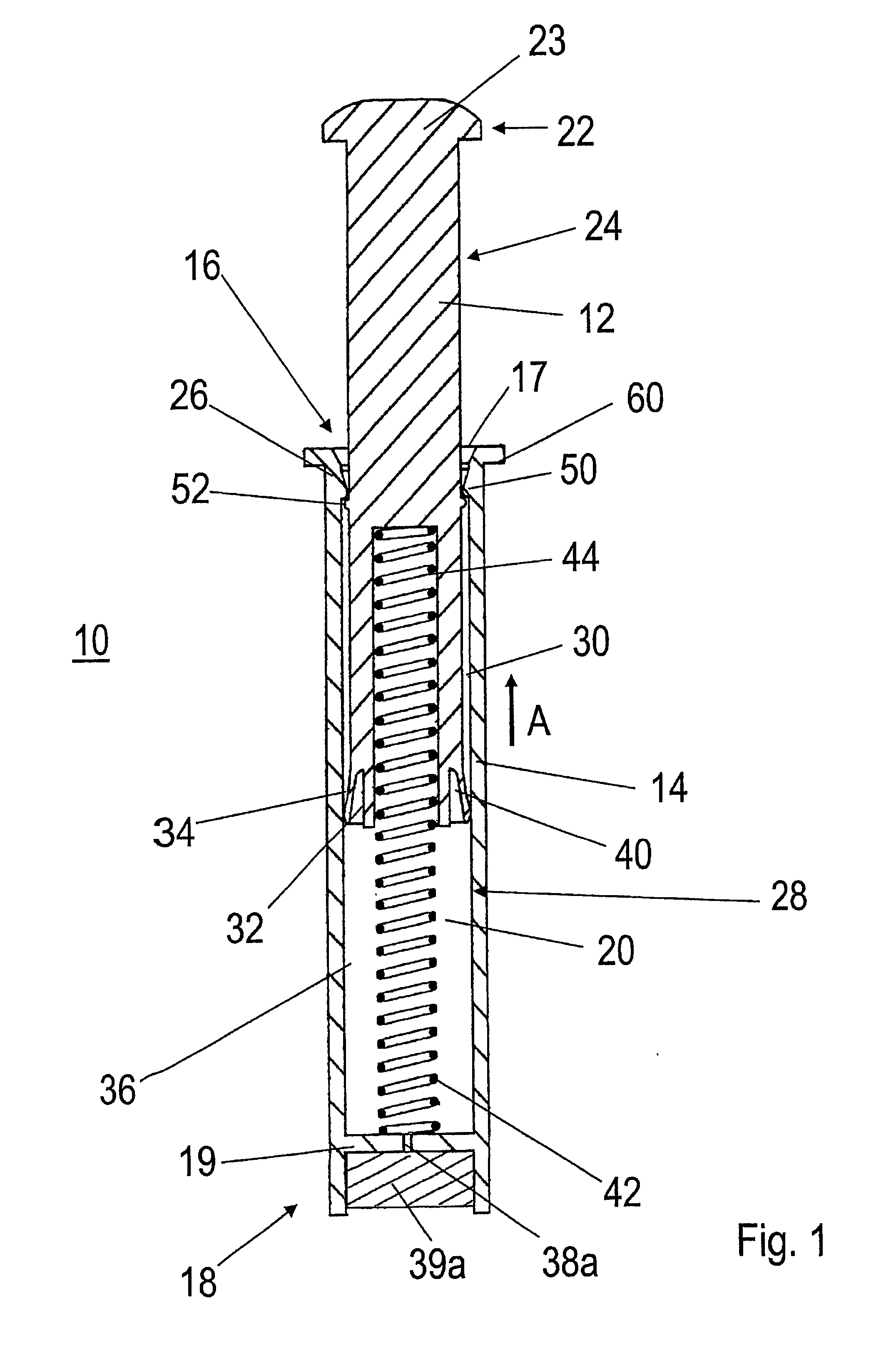
[0033] This invention is explained in greater detail in view of exemplary embodiments represented in the drawings, wherein:

[0034]FIG. 1 shows a door-closing damper in a lateral and sectional view, in accordance with one embodiment, having a damping member arranged at the closed end of the damper body, and with the sliding element completely extended;

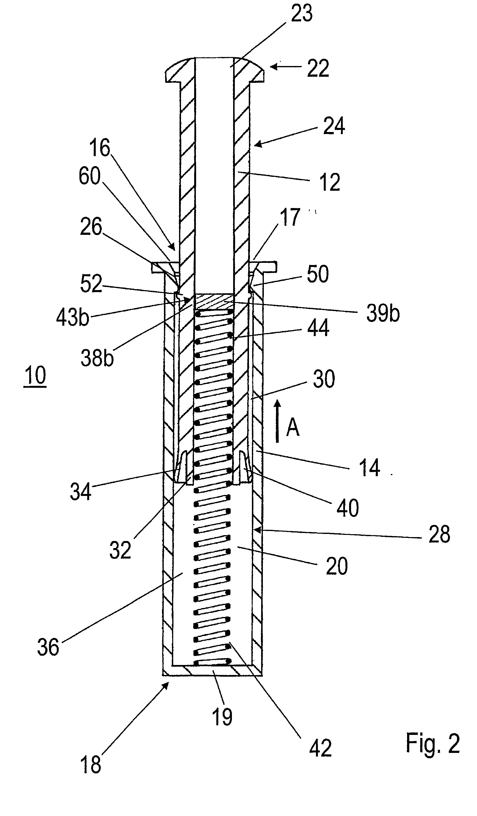
[0035]FIG. 2 shows a door-closing damper in a lateral and sectional view in accordance with a further embodiment, having a damping member arranged at the sliding element, wherein the sliding element is shown completely extended;

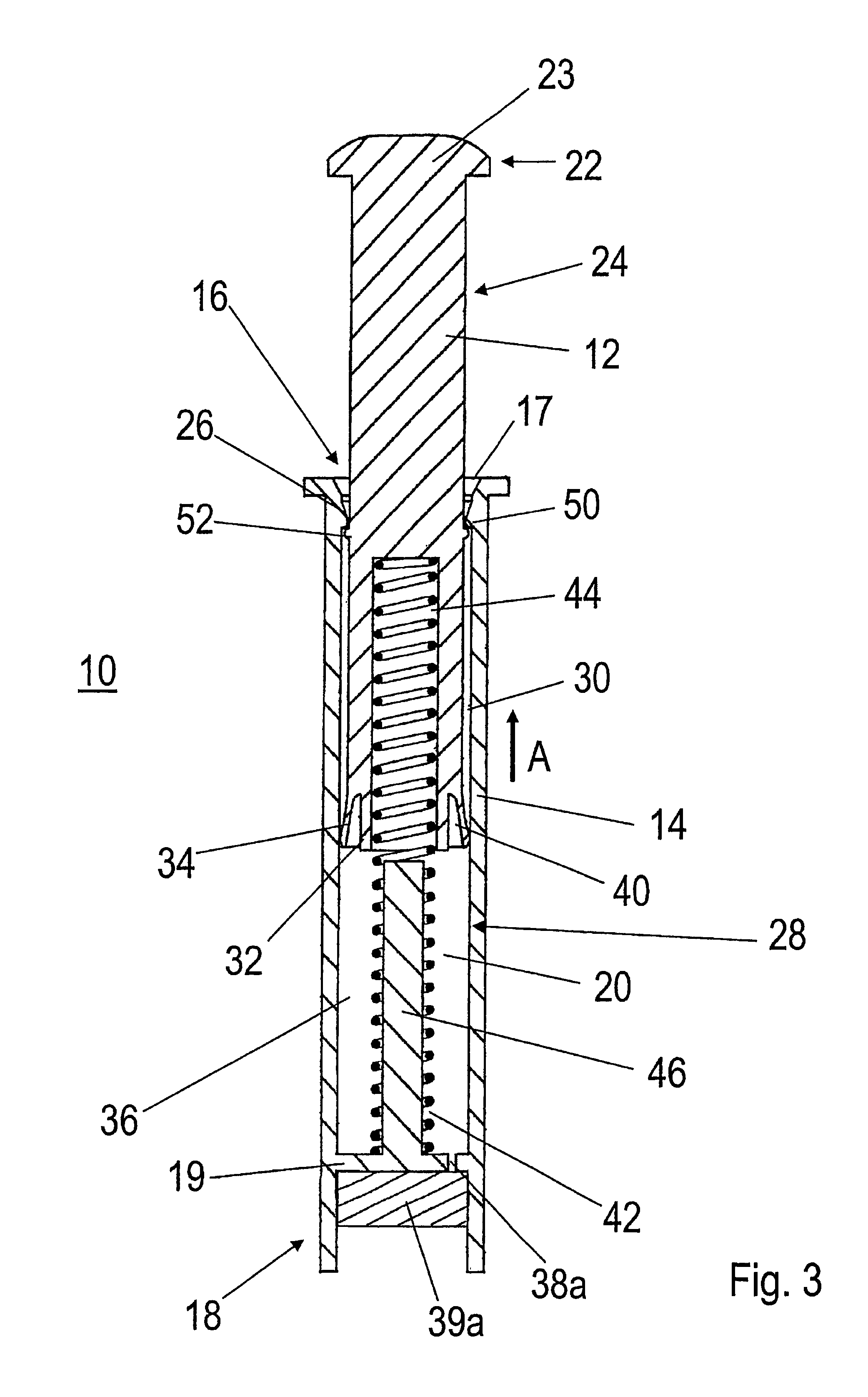
[0036]FIG. 3 shows a door-closing damper in a lateral and sectional view in accordance with a still further embodiment, having a damping member arranged at the closed end of the damper body, a pin arranged in the hollow chamber, and with the sliding element completely extended;

[0037]FIG. 4 shows a door-closing damper in accordance with FIG. 3, in a lateral and sectional view, with the sliding element completel...


PUM


Abstract

An end stop damper including a stop element, guided in an elongate damper body with an opened and a closed end as well as a receiving chamber, for receiving a sliding piece, joined to the stop element. The end of the sliding piece, which extends into the receiving chamber, forms a cavity with the inner contour of the receiving chamber. The cavity has at least one opening, for reducing the air pressure. The opening cooperates with a damping element which creates a flow resistance for the air, escaping through the opening.

Description

BACKGROUND OF THE INVENTION [0001] 1. Field of the Invention [0002] This invention relates to a door-closing damper, such as is used in the manufacture of furniture, and particularly for furniture doors and drawers. [0003] 2. Discussion of Related Art [0004] Damping elements are known which are used to let the doors and drawers of furniture return gently into their closed end position. It is intended to prevent an abrupt and therefore annoying touching of parts of furniture, to limit wear and to obtain a noise-damping and shock-damping effect. [0005] The known damping elements substantially have an elastic stop element fixed in a blind bore cut into the furniture body. The stop element can also be glued on the furniture body. Such a stop element protrudes beyond the flat surface of the piece of furniture and, because of its elastic deformability, it lessens the impact of a further furniture element, such as a furniture door, for example. [0006] However, one problem arises with cabin...

Claims


Application Information

Patent Timeline
Patent Type & Authority Applications(United States)
IPC IPC(8): E05F5/02E05F5/08E05F5/10F16F9/10F16F9/34F16F13/00
CPCE05F5/02E05F5/08E05F5/10E05Y2201/21E05Y2201/212E05Y2201/256E05Y2201/264E05Y2201/474F16F9/10F16F9/3415F16F13/007
Inventor BANTLE, ULRICHESCHLE, JUERGEN
Owner KARL SIMON GMBH & CO KG
Why Eureka
Try Eureka