Driving a matrix display

Inactive Publication Date: 2007-11-29
KONINKLIJKE PHILIPS ELECTRONICS NV
View PDF5 Cites 22 Cited by
  • Summary
  • Abstract
  • Description
  • Claims
  • Application Information

AI Technical Summary

Benefits of technology

[0022] The only difference between the embodiment in accordance with the invention as claimed in claim 6 and the embodiment as claimed in claim 4 is that now the drive signals instead of the input signals are stored in the frame memory. This

Problems solved by technology

However, the LC material in the current LCD panels is too slow to be able to display all desired pixel brightness transitions within a single frame time which results in blurred moving images.
However, due to the inertia of the LC material it may take several frames until the pixel has reached this high brightness

Method used


Image

  • Driving a matrix display
  • Driving a matrix display
  • Driving a matrix display

Examples


Example

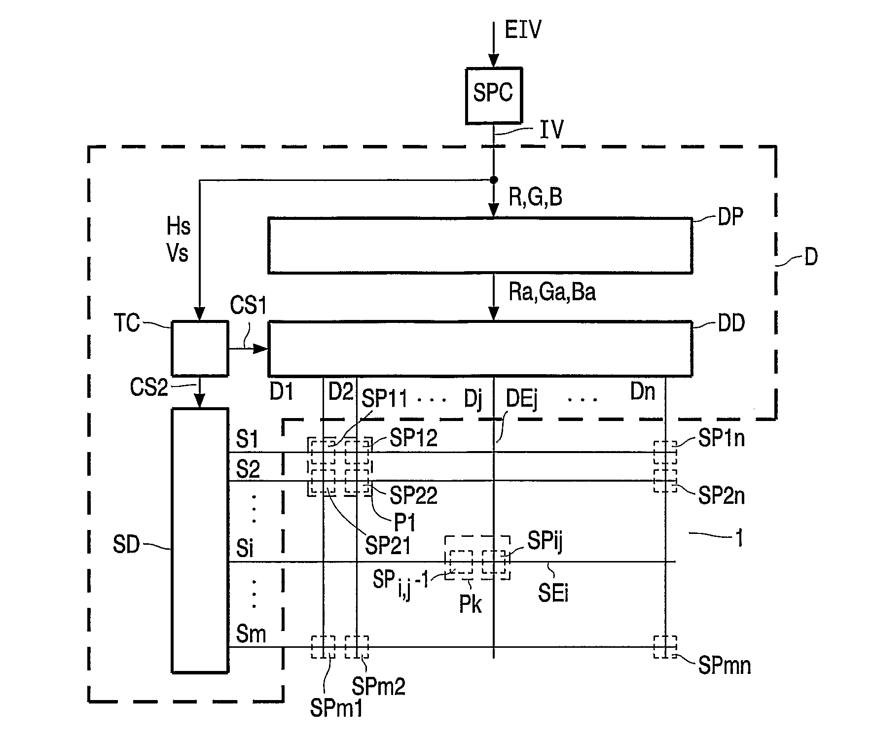
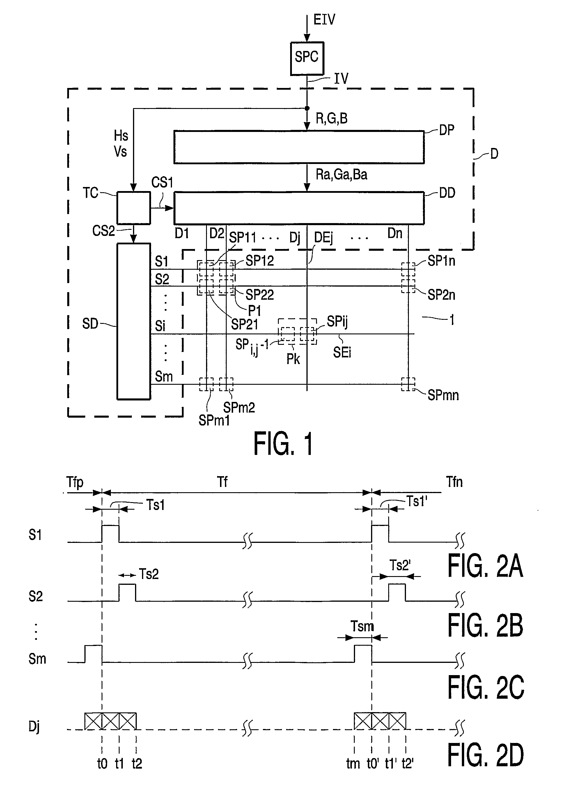
[0042]FIG. 1 shows a block diagram of a display apparatus. The display apparatus comprises signal processing circuitry SPC and a display device comprising a driver D an a matrix display panel 1. The matrix display panel 1 comprises sub-pixels SPij (SP11, SP12, SP21, SP22, SP1n, SP2n, SPm1, SPm2, SPmn) which are associated with intersecting select electrodes SEi and data electrodes DEj. The index i indicates the select electrode SEi involved, the index j indicates the data electrode DEj involved. By way of example only, the matrix display panel 1 shown in FIG. 1 has square sub-pixels SPij and pixels Pk which each comprise four sub-pixels SPij (the pixel P1 indicated comprises the sub-pixels SP11, SP12, SP21, and SP22). The sub-pixels SPij may have other dimensions such as oblong rectangles; the pixels Pk may comprise less or more than three sub-pixels SPij. The four sub-pixels SP11, SP12, SP21, SP22 of the pixel P1 may have the colors red, green, blue and white in any order. The indi...


PUM


Abstract

A driver (D) for a matrix display panel (1) with a pixel (Pk) comprising a first and a second sub-pixel (SP11, 12) both having an inertia, receives a first and second input signal (R, G) indicating a first and a second desired brightness transition (BT1, BT2) of the first and second sub-pixel (SP11, 12), respectively. The driver (D) supplies a first and a second drive signal (Ra, Ga) to the first and the second sub-pixel (SP11, 12), respectively. The first and a second drive signal (Ra, Ga) are supplied at a predetermined repetition rate, and levels of the first and the second drive signal (Ra, Ga) are limited between a minimum level (MI) and a maximum level (MA). The predetermined repetition rate may be the frame or line rate. The predetermined period is the reciprocal of the predetermined repetition rate. The driver (D) comprises: a detector (LV1) which detects whether the first drive signal (Ra) within the single predetermined period (Tf) would have to surpass the maximum level (MA) or to fall below the minimum level (MI) in order to compensate for the inertia of the first sub-pixel (SP11), and a level adapter (AC) which increases or decreases a level of the second drive signal (Ga) if is detected that the first drive signal (Ra) would have to surpass the maximum level (A) or fall below the minimum level (MI), respectively.

Description

FIELD OF THE INVENTION [0001] The invention relates to a driver for a matrix display panel, to a display device comprising the driver, and to a method of driving a matrix display panel. BACKGROUND OF THE INVENTION [0002] LCD (liquid crystal display) panels are increasingly used to display moving video content, for example in television receivers and computer monitors. However, the LC material in the current LCD panels is too slow to be able to display all desired pixel brightness transitions within a single frame time which results in blurred moving images. This problem can partly be mitigated with the well-known technique of overdrive. With overdrive, the pixels are driven with a higher level than the desired level. For example, if a pixel has to make a brightness transition from a low brightness value to a high brightness value, a level associated to the high brightness value has to be supplied to the pixel to obtain this high brightness value in the stable situation. However, due...

Claims


Application Information

Patent Timeline
IPC IPC(8): G09G5/10G09G3/34G09G3/36
CPCG09G3/34G09G2340/16G09G2320/0261G09G3/3607G09G3/36G02F1/133G09G3/20
Inventor WUBBEN, ROBERTUS HENDRICUS MARIAHEKSTRA, GERBEN JOHAN
Owner KONINKLIJKE PHILIPS ELECTRONICS NV
Why Eureka
Try Eureka