Method for detecting and localizing faults in an optical transmission path, and optical transmission system

Active Publication Date: 2007-11-29
DEUTSCHE TELEKOM AG
View PDF7 Cites 21 Cited by
  • Summary
  • Abstract
  • Description
  • Claims
  • Application Information

AI Technical Summary

Benefits of technology

[0039] transition cables (so-called patch cords) to connect the system via plug connections, essentially inside buildings. In embodiments of the present invention, the optical components, may be able to cause changes in the polarization. The mechanical configuration and the related thermal capacity or insulation of the optical components determine the sensitivity of the components/network elements wit

Problems solved by technology

For example, in the case of a subterranean glass-fiber infrastructure, the glass-fiber cables may be destroyed by external causes.
A main cause of such destruction can be construction work.
However, mechanical influences that h

Method used


Image

  • Method for detecting and localizing faults in an optical transmission path, and optical transmission system
  • Method for detecting and localizing faults in an optical transmission path, and optical transmission system
  • Method for detecting and localizing faults in an optical transmission path, and optical transmission system

Examples


Example

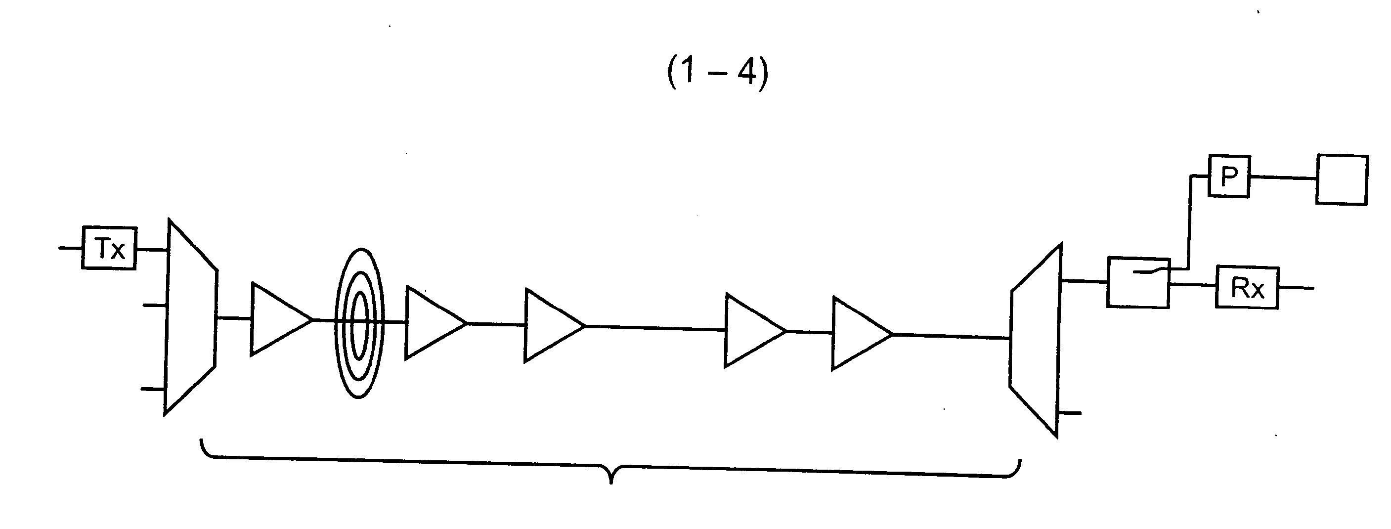
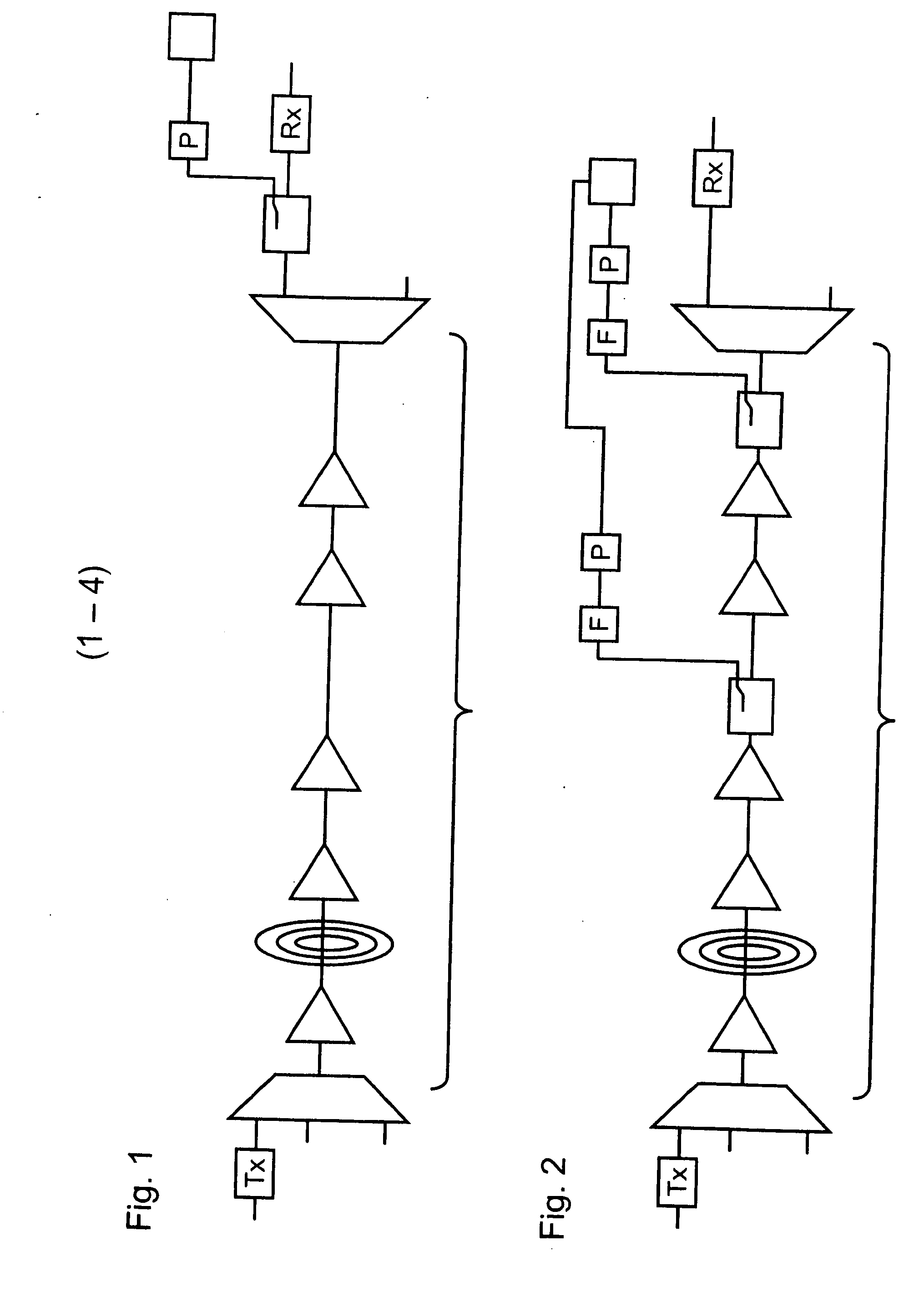
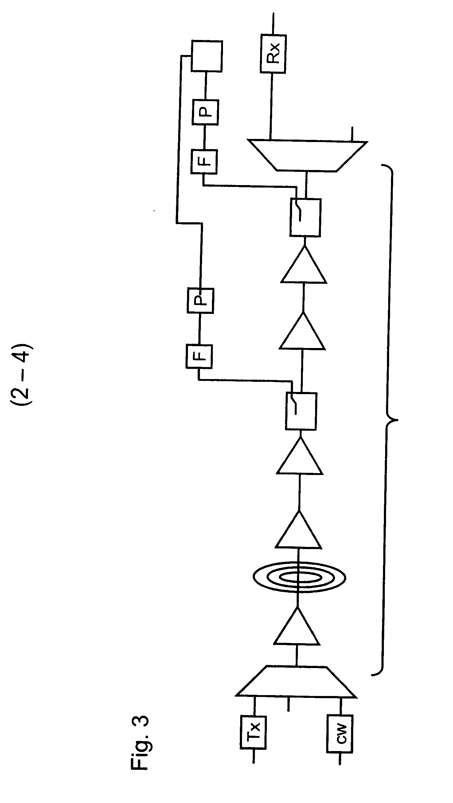
[0048]FIG. 1 shows an example of a transmission system 1 having functionality according to the present invention. The data signals are multiplexed with a multitude of transmitters, of which only one transmitter 12 is shown, using a multiplexer 14, and transmitted via fiber 19, i.e., transmission path 20. Transmission path 20 may be a few hundred or even a few thousand kilometers in length. The data signal is boosted at predefined intervals by means of amplifiers 22 through 26 in transmission path 20. The distance between the amplifiers may typically be on the order of magnitude of 50 km. The number of amplifiers is an example. At the end of transmission path 20 the bundled signals are de-multiplexed again with the aid of a de-multiplexer 34, and received by receivers, of which only one receiver 32 is shown.

[0049] In this embodiment, a portion of the signals used for the transmission of information is decoupled directly at the output of de-multiplexer 34 in front of receiver 32 by m...


PUM


Abstract

A method for detecting and locating faults in an optical transmission path, and to an optical transmission system having such a functionality, is provided. By measuring the temporal change in the state of polarization SOP, external influences on a glass fiber cable of a long-haul transmission system, e.g., a WDM transmission system, may be detected. Such fault(s) may be localized with the aid of the relative arrival time of the polarization signal at both sides of a bidirectional transmission system.

Description

FIELD OF THE INVENTION [0001] The present invention relates to a method for detecting and localizing faults in an optical transmission path, and to an optical transmission system having such a functionality. BACKGROUND INFORMATION [0002] The importance of optical data transmission, especially across long distances, has grown enormously over the past few decades. [0003] Long-range, so-called wave division multiplex systems (WDM) having optical amplifiers form the basis of high-capacity transmission networks, so-called backbone networks, in the long-distance range. In a WDM system, a multitude of carrier signals having different wavelengths is transmitted simultaneously via the same optical fiber. Typical distances that are able to be bridged in an optically transparent manner are in the range of 200 km to 2000 km. Optical transmission systems are utilized to guide the data to the backbone networks; these optical transmission systems are likewise based on glass fiber and are partly ba...

Claims


Application Information

Patent Timeline
IPC IPC(8): H04B10/08H04B10/07H04B10/079
CPCG01M11/332H04B10/07H04J14/06H04J14/02H04B10/0791
Inventor LEPPLA, RALPHSCHNEIDERS, MALTEVORBECK, SASCHAWEIERSHAUSEN, WERNERRUMPF, FRANKGUNKEL, MATTHIAS
Owner DEUTSCHE TELEKOM AG
Why Eureka
Try Eureka