Device for suturing intracardiac defects

a technology of intracardiac defect and suture device, which is applied in the field of transcatheter devices and methods for suturing intracardiac defects, can solve the problems of pfo's complex anatomical structural features, and affecting the clinical outcom

Active Publication Date: 2007-11-29
ABBOTT LAB INC
View PDF99 Cites 25 Cited by
  • Summary
  • Abstract
  • Description
  • Claims
  • Application Information

AI Technical Summary

Problems solved by technology

The anatomical structural features of PFO's, however, are more complex.
Septum secundum is thicker than septum primum and exhibits limited mobility and compliance.
This later measure ultimately limits the potential size of the PFO.
The long central section, however, increased bulkiness of the device.
Furthermore, we subsequently observed that the central body of the double disc device actually displaced the relatively compliant septum primum, thus shortening the length of the PFO tunnel.
After device placement, the long central pin unnecessarily increased the device profile in the heart, thus potentially preventing complete endothelialization.
Any relatively rigid device that failed to anticipate changes in the topography of the atrial septum could have similar drawbacks.
Thus placement of a device designed for the static rather than the compliant anatomy of the atrial septum could fail to meet the needs of patients with PFO and a history of cryptogenic stroke.” Id.
Ventricular septal defects clearly present challenging substrates for closure devices, often with irregularly configured defect in a thick, muscular septum.
For example, many of the devices require complex loading devices for delivery of the device to the defect.
Additionally, many of the devices require time consuming positioning and deployment procedures which have a high margin for error.
Still further, many of the devices require extensive remote manipulation to anchor or deploy the device, this not only increases the amount of time required to deploy the device but also increases the likelihood of errors during deployment.
Lastly, each of the devices in their expanded and deployed condition leave a large surface area of material within the patient's body, wherein this large area of material may lead to the formation of thromobosis or cause a reaction in the patient's body.

Method used


Image

  • Device for suturing intracardiac defects
  • Device for suturing intracardiac defects
  • Device for suturing intracardiac defects

Examples


Embodiment Construction

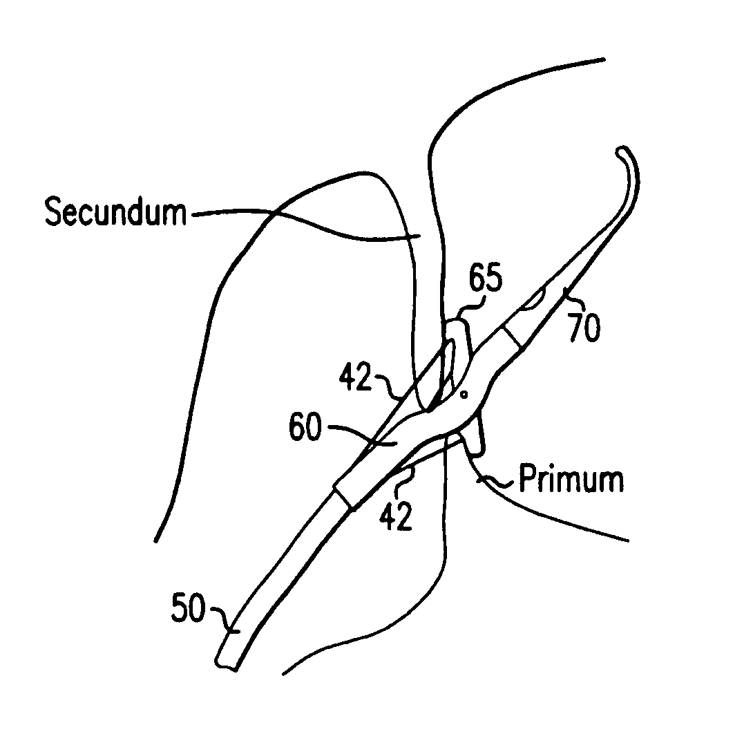
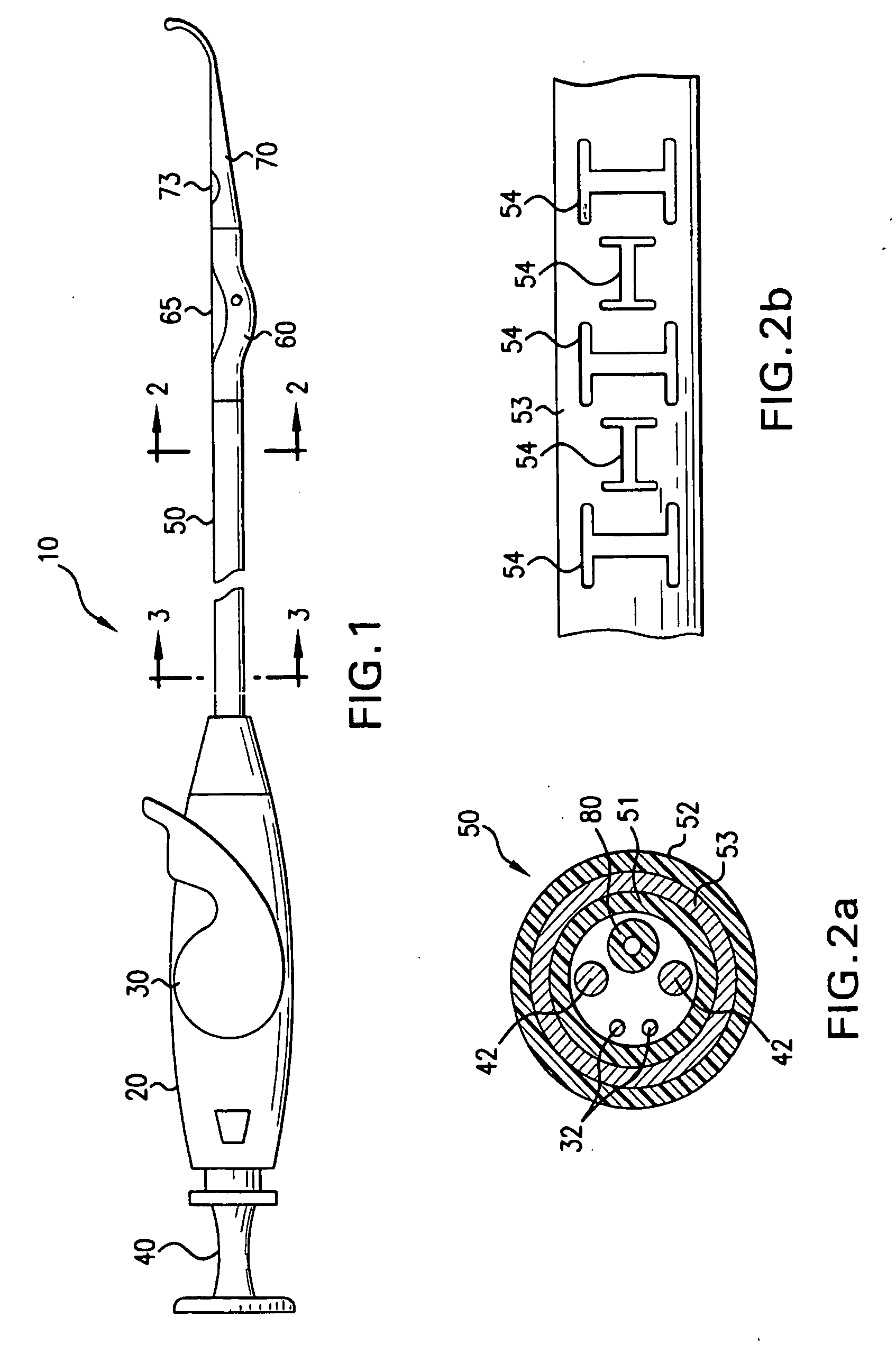
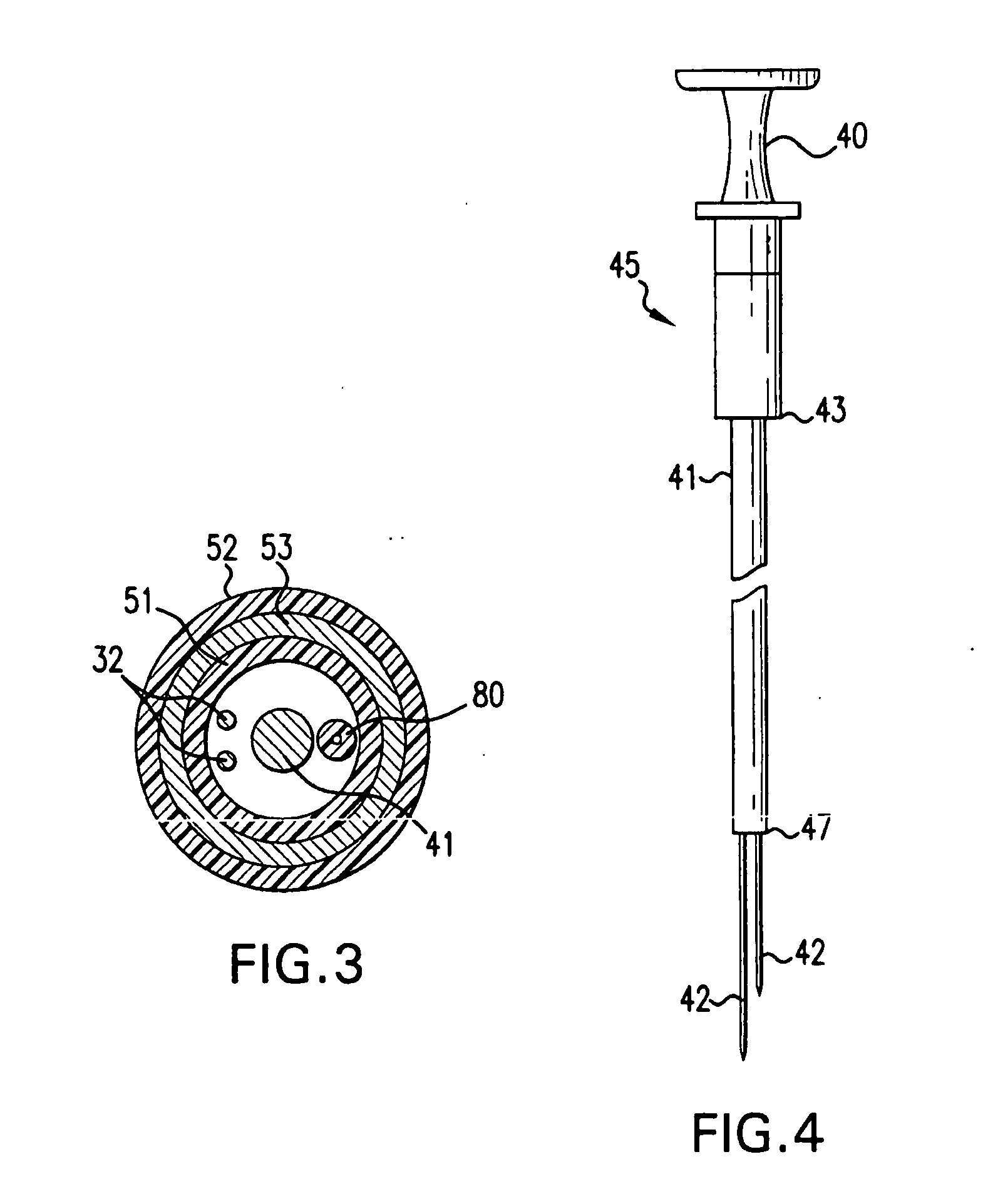
[0045] In accordance with the present invention there is provided a device and methods for closing intracardiac defects. The device according to the present invention include a handle portion, a flexible elongated member extending from the handle portion at one end and connected to a foot housing at the other end, a deployable foot disposed within the foot housing and a flexible distal tip. At least one needle and more preferably two needles are disposed within the flexible elongated member. The suturing device is configured to dispose a length of suture across the site of a PFO, wherein the suture is placed through the tissue adjacent the opening to close the opening. As described in more detail below, the suture is advanced through the tissue by a pair of needles that penetrate the tissue adjacent the opening, connect with the ends of the suture, and move the suture through the penetrations in the tissue to span the opening. A knot is then loosely tied with the length of suture an...


PUM


Abstract

In accordance with the present invention there is provided a suturing device. The suturing device includes a length of suture that will be delivered to the site of the PFO and placed through the tissue adjacent the opening to close the PFO. As described in greater detail below, the suture is advanced through the tissue surrounding the opening by a pair of needles that penetrate the tissue adjacent to the opening. A knot is then loosely tied with the length of suture and advanced to the site of the PFO. The tails of the suture extending from the knot are then cut and removed. It is also contemplated that a pre-formed or pre-tied knot may be disposed on the device, wherein after deployment of the suture through the tissue adjacent to the PFO and removal of the device a loop of suture having a pre-tied knot will remain, wherein the pre-tied knot may then be tightened to close the PFO. Further still it is contemplated that other means may be utilized to retain the sutures. For example, it is contemplated that a suture clip or other clip like device may be utilized to retain the suture in a position such that the PFO is closed.

Description

RELATED APPLICATION DATA [0001] The present application is a continuation application of U.S. application Ser. No. 10 / 948,445, naming Scott A. McIntosh as inventor, filed Sep. 22, 2004 and entitled DEVICE AND METHOD FOR SUTURING INTRACARDIAC DEFECTS; which in turn claims priority to the following U.S. Provisional Patent applications having Ser. Nos. 60 / 506,536 and 60 / 540,811 filed on Sep. 26, 2003 and Jan. 30, 2004 the entireties of which all are herein incorporated by reference. [0002] This application is also related to the following U.S. patent applications: [0003] application Ser. No. 10 / 660,288, filed Sep. 11, 2003; [0004] application Ser. No. 10 / 652,182, filed Aug. 29, 2003; [0005] application Ser. No. 10 / 357,984, filed Feb. 4, 2003; [0006] application Ser. No. 10 / 152,272, filed May 20, 2002; [0007] application Ser. No. 09 / 651,344, filed Aug. 29, 2000; and application Ser. No. 09 / 262,402, filed on Mar. 4, 1999, now U.S. Pat. No. 6,136,010. [0008] The disclosures of application...

Claims


Application Information

Patent Timeline
Patent Type & Authority Applications(United States)
IPC IPC(8): A61B17/03A61B17/00A61B17/04A61B17/06A61B17/122A61B19/00
CPCA61B17/0469A61B17/122A61B19/54A61B2017/00575A61B2017/00592A61B17/0491A61B2017/00615A61B2017/0472A61B2017/0475A61B2017/0477A61B2017/00597A61B90/39A61B2017/00243
Inventor MCINTOSH, SCOTT A.
Owner ABBOTT LAB INC
Why Eureka
Try Eureka