Suture clip

A technology for closing clips and clamping arms, which is applied in the field of medical devices and can solve problems such as unfavorable for minimally invasive surgery, increased volume of closed clips, and increased surgical implant path size.

Pending Publication Date: 2020-11-10
BEIJING LINGJIAN MEDICAL TECH CO LTD
View PDF0 Cites 1 Cited by
  • Summary
  • Abstract
  • Description
  • Claims
  • Application Information

AI Technical Summary

Problems solved by technology

Because the spring arm and the clip arm are not in the same plane, the volume of the closure clip increases,

Method used


Image

  • Suture clip
  • Suture clip
  • Suture clip

Examples


Embodiment 1

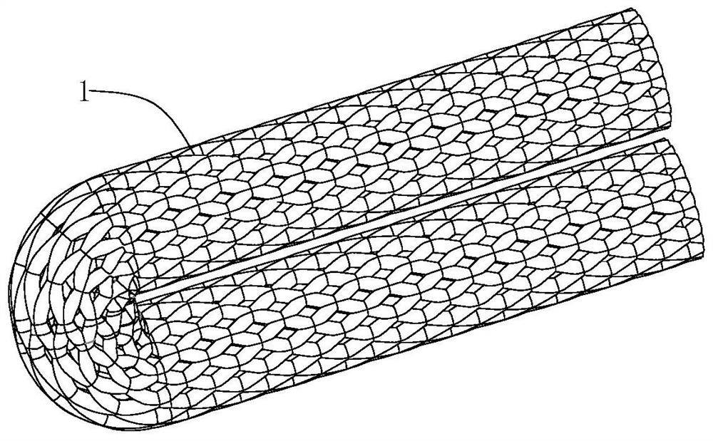
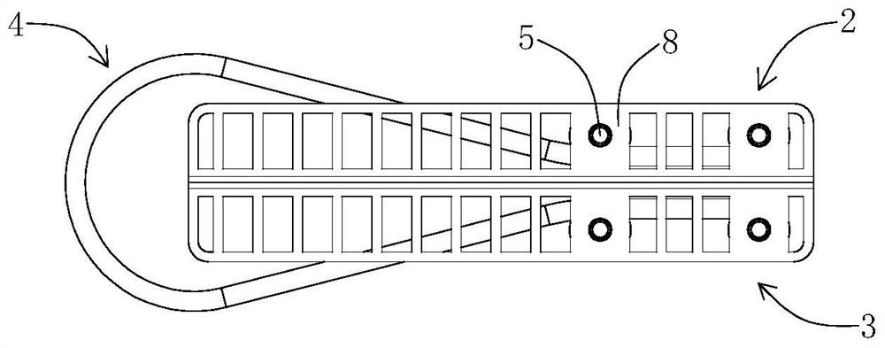
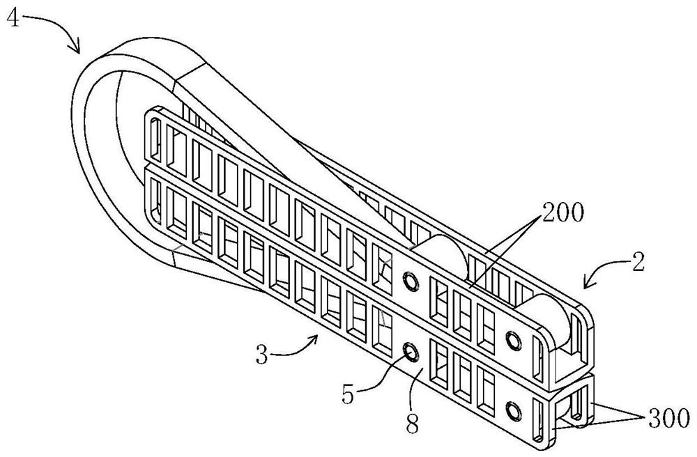
[0078] Such as figure 1 shown, combined with Figure 2-11 As shown, the closure clip of the present invention includes a first clip arm 2, a second clip arm 3, an elastic clip 4 and a sleeve 1, the first clip arm 2 and the second clip arm 3 are arranged oppositely, and the elastic clip 4 is arranged along the The length direction of the first clip arm 2 and the second clip arm 3 is arranged, and the ends of the two elastic clip arms of the elastic clip 4 are respectively provided with closing arms 401, and the two closing arms 401 are clamped on the first clip respectively. The outer side 11 distal ends of the arm 2 and the second clamp arm 3, the first clamp arm 2, the elastic clamp 4 and the second clamp arm 3 are sequentially accommodated in the sleeve 1, and the sleeve 1 adopts a Tubular pieces made of biocompatible materials, such as PET threads.

[0079] The closure clip of the present invention, wherein the outer surface 11 of the first clamp arm 2 is provided with tw...

Embodiment 2

[0089] Such as figure 1 shown, combined with Figure 12-21 As shown, the difference between this embodiment and Embodiment 1 is that only one first through hole 9 is provided on the two closing arms 401 of the elastic clip 4, and the first through hole 9 is arranged at the end of the closing arm 401, correspondingly Yes, only one second through hole 7 is provided on the first thin wall 200 and the second thin wall 300 .

Embodiment 3

[0091] Such as figure 1 shown, combined with Figure 22-31 As shown, the difference between the present embodiment and the second embodiment is that each of the two closing arms 401 is provided with a first through hole 9, and each first through hole 9 runs through the inner surface and the outer surface of the closing arm 401 where it is located. A second through hole 7 corresponding to the first through hole 9 is provided on the outer surface of the first clamping arm 2 and the second clamping arm 3 . A pin 5 is inserted through the first through hole 9 and the second through hole 7 corresponding to each other, and the pin 5 is fixedly arranged in the first through hole 9 and the second through hole 7 corresponding to each other by means of riveting or welding, namely : the second through hole 7 on the first clamp arm 2 and the first through hole 9 on a closing arm 401 of the elastic clip 4 are fixedly provided with the pin 5, the second through hole 7 on the second clamp a...


PUM


Abstract

The invention discloses a suture clip. The suture clip comprises a first clamping arm, a second clamping arm, an elastic clamp and a sleeve, wherein the first clamping arm and the second clamping armare oppositely arranged, the elastic clamp is arranged in the length direction of the first clamping arm and the second clamping arm, and closing arms are arranged at the ends of the two elastic clamping arms of the elastic clamp respectively. The two closing arms are respectively clamped at the far ends of the outer side surfaces of the first clamping arm and the second clamping arm, the first clamping arm, the elastic clamp and the second clamping arm are sequentially accommodated in the sleeve, and the sleeve is made of a material having biological tissue compatibility. The invention aims to provide the suture clip which is small in size and can realize single-end opening.

Description

technical field [0001] The invention relates to a medical device, in particular to a device for sealing human tissue in minimally invasive surgery. Background technique [0002] Clinically, it is usually necessary to close the target tissue to treat or prevent a certain disease. During this process, it is necessary to use a special delivery device to deliver the closure clip into the human body and open it to capture the target tissue, so that the target tissue is clamped in the closed state. The closure is completed between the two clamp arms of the clamp. The closing clamp is provided with a spring arm, and under the action of the spring arm, the closing clamp can be closed. When the existing closing clamp is closed, both ends are used to clamp and close, that is, two spring arms are used to clamp the clamp arm respectively. The two ends are closed, and the spring arm and the clip arm are not in the same plane. Since the closure clip is closed at both ends, the lasso can...

Claims


Application Information

Patent Timeline
IPC IPC(8): A61B17/122
CPCA61B17/1227A61B2017/00243A61B17/122
Inventor 周晓军谢晨光谢北平
Owner BEIJING LINGJIAN MEDICAL TECH CO LTD
Why Eureka
Try Eureka