
Firearm target illumination implement

a technology for illumination implements and firearms, applied in the field of firearm implements, can solve problems such as several known problems

Inactive Publication Date: 2007-12-06
LEAPERS
View PDF93 Cites 57 Cited by
  • Summary
  • Abstract
  • Description
  • Claims
  • Application Information

AI Technical Summary

Benefits of technology

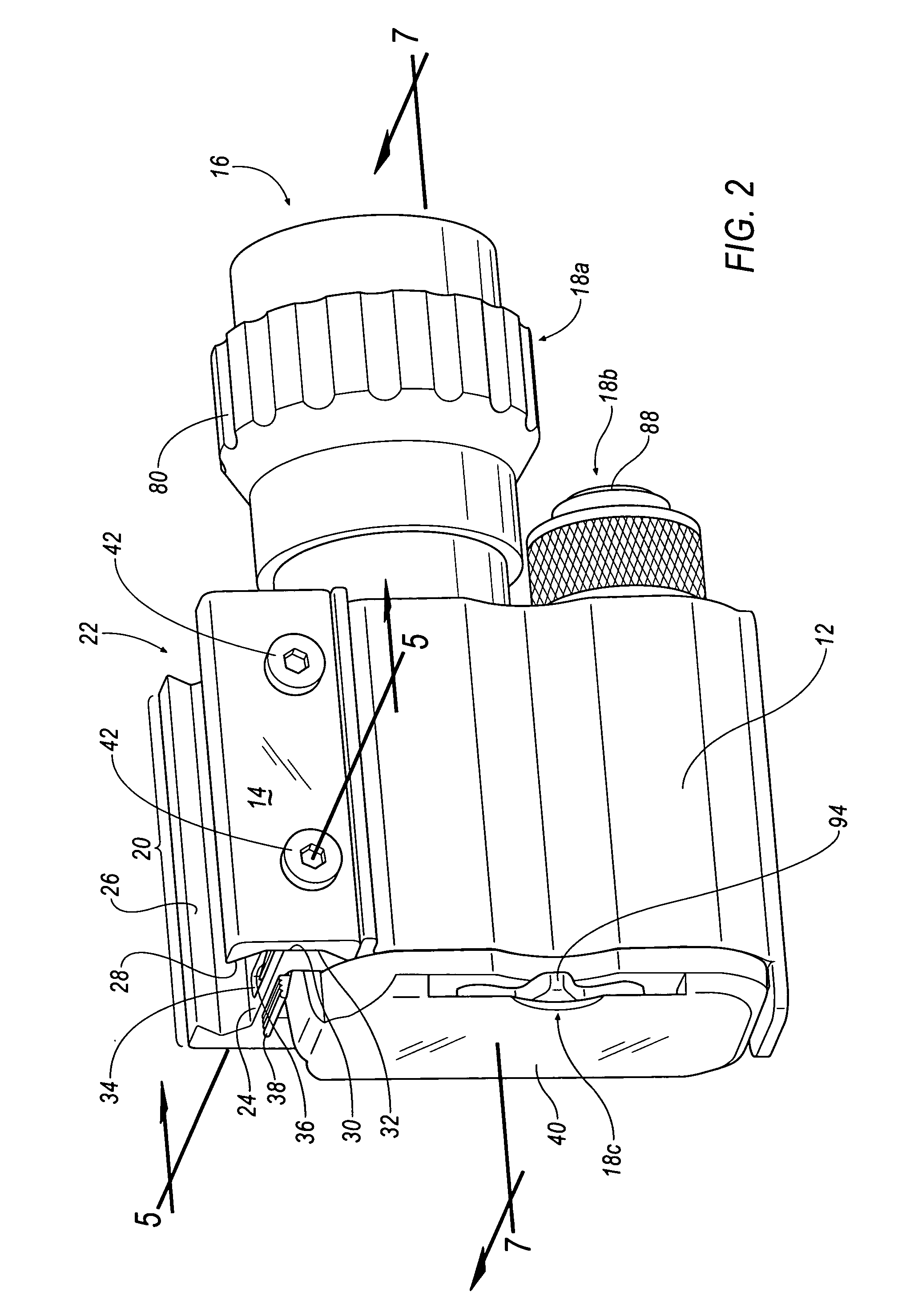
[0004]According to an embodiment, the firearm target illumination implement includes an illumination device disposed in the body and a plurality of illumination device actuators ambidextrously-arranged on the body to provide control of on / off switching and focusing of light emitted from the illumination device.
[0005]According to an embodiment, the firearm target illumination implement includes a mounting plate that is removably-secured to the body, at least one fastener that passes through the mounting plate and into the body, and a portion of the at least one fastener that provides tactile feedback to an operator when the at least one fastener is moved by the operator from a first position to a second position.
[0006]According to an embodiment, the firearm target illumination implement includes two or more axes extending, respectively, through the two or more energy cell cavities formed in the body that are parallel to but not coincident with a axis of the barrel of the firearm.

Problems solved by technology

Although adequate in providing illumination of a target, conventional firearm target illumination implements are known to have several limitations regarding 1) weight, 2) size, 3) universal adaptability to a plurality of firearms, 4) firearm operator reach of illumination focus / on / off features, and the like.

Method used


Image

  • Firearm target illumination implement
  • Firearm target illumination implement
  • Firearm target illumination implement

Examples


Embodiment Construction

[0022]Referring now to the drawings, the preferred illustrative embodiments of the present disclosure are shown in detail. Although the drawings represent some preferred embodiments of the present disclosure, the drawings are not necessarily to scale and certain features may be exaggerated to better illustrate and explain the present disclosure. Further, the embodiments set forth herein are not intended to be exhaustive or otherwise limit or restrict the disclosure to the precise forms and configurations shown in the drawings and disclosed in the following detailed description.

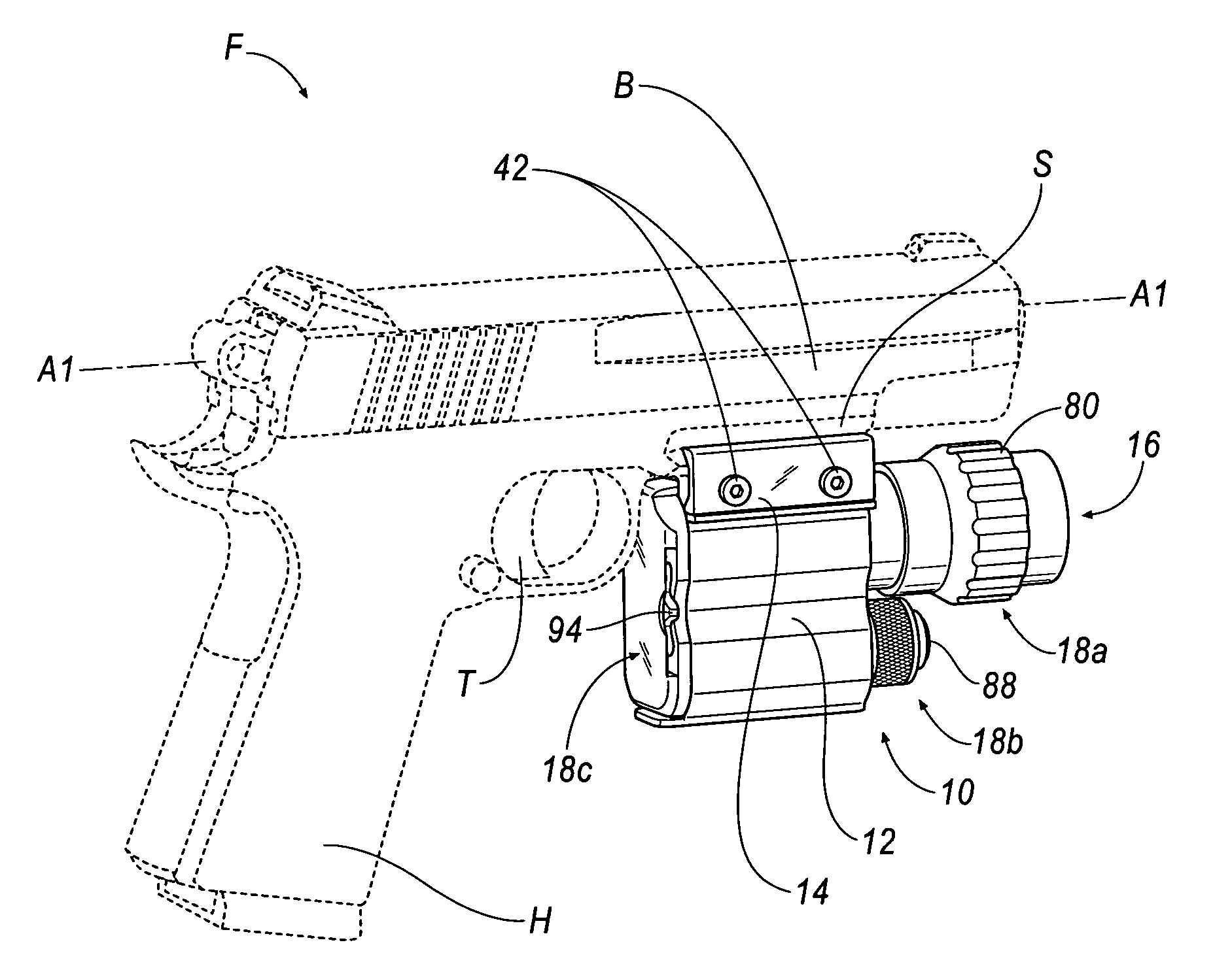
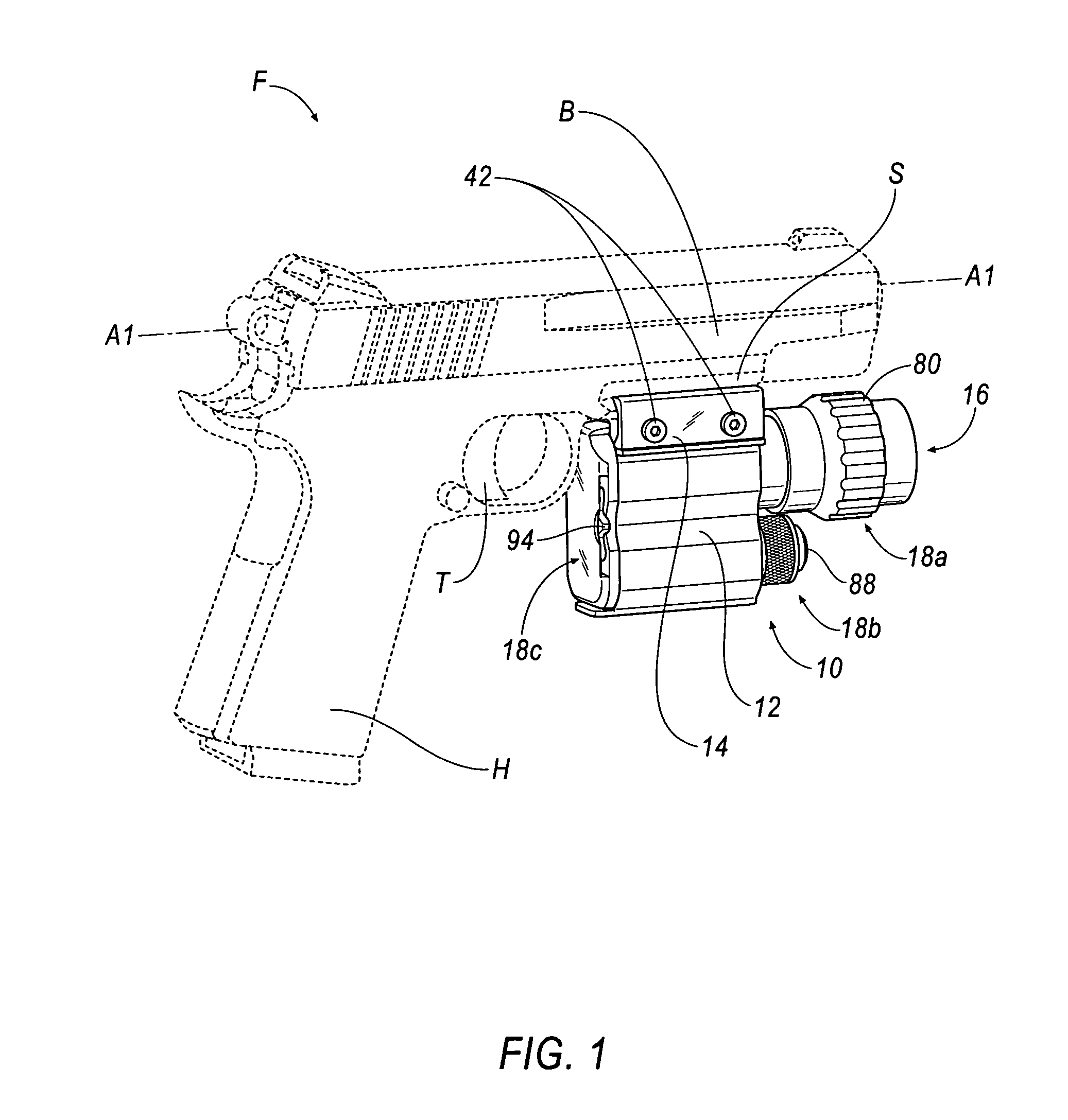
[0023]Referring to FIG. 1, an exemplary firearm is shown generally at F (in phantom). The firearm, F, may be, for example, a pistol, handgun, revolver, or the like. The illustrated firearm, F, according to an embodiment, is a pistol and is shown to include a barrel, B, one or more barrel rail slot(s), S, a handle grip, H, and a trigger, T. An axis of the barrel, B, is shown generally at A1, according to an emb...


PUM


Abstract

A firearm target illumination implement is disclosed. The firearm target illumination implement includes a body that is adapted for removable-attachment to a barrel of a firearm. According to an embodiment, the firearm target illumination implement includes an illumination device disposed in the body and a plurality of illumination device actuators ambidextrously-arranged on the body to provide control of on / off switching and focusing of light emitted from the illumination device. According to an embodiment, the firearm target illumination implement includes a mounting plate that is removably-secured to the body, at least one fastener that passes through the mounting plate and into the body, and a portion of the at least one fastener that provides tactile feedback to an operator when the at least one fastener is moved by the operator from a first position to a second position. According to an embodiment, the firearm target illumination implement includes two or more axes extending, respectively, through the two or more energy cell cavities formed in the body that are parallel to but not coincident with a axis of the barrel of the firearm.

Description

FIELD OF THE INVENTION[0001]The disclosure relates to firearm implements and, more particularly, to a firearm implement that provides target illumination.DESCRIPTION OF THE RELATED ART[0002]It is known in the art that firearm implements may include, for example, flashlights that illuminate a target in low lighting conditions for a firearm operator. Although adequate in providing illumination of a target, conventional firearm target illumination implements are known to have several limitations regarding 1) weight, 2) size, 3) universal adaptability to a plurality of firearms, 4) firearm operator reach of illumination focus / on / off features, and the like. Accordingly, a need therefore exists for an improved firearm target illumination implement that is light in weight, compact in size, configured to be secured to more than one firearm, and is adapted for quick and ambidextrous access / activation of illumination features and the like.SUMMARY OF THE INVENTION[0003]A firearm target illumin...

Claims


Application Information

Patent Timeline
Patent Type & Authority Applications(United States)
IPC IPC(8): F41G1/00
CPCF41G11/003F41G1/35
Inventor DING, TAI LAI
Owner LEAPERS
Learn More