Refill device for dispensing a cosmetic product

a refill device and cosmetic product technology, applied in the direction of containers, liquid bottling, packaging goods, etc., can solve the problem of limited product decanting or transfer

Inactive Publication Date: 2007-12-06
ALCAN PACKAGING BEAUTY SERVICES
View PDF0 Cites 28 Cited by
  • Summary
  • Abstract
  • Description
  • Claims
  • Application Information

AI Technical Summary

Benefits of technology

[0018]Decanting or transfer of product w...

Problems solved by technology

Indeed, on one hand, product decanting or transfer is limited to two basic operations, with:the vaporization head being unscrewed in order to disengage the ...

Method used


Image

  • Refill device for dispensing a cosmetic product
  • Refill device for dispensing a cosmetic product
  • Refill device for dispensing a cosmetic product

Examples


example 1

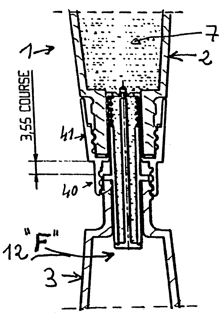
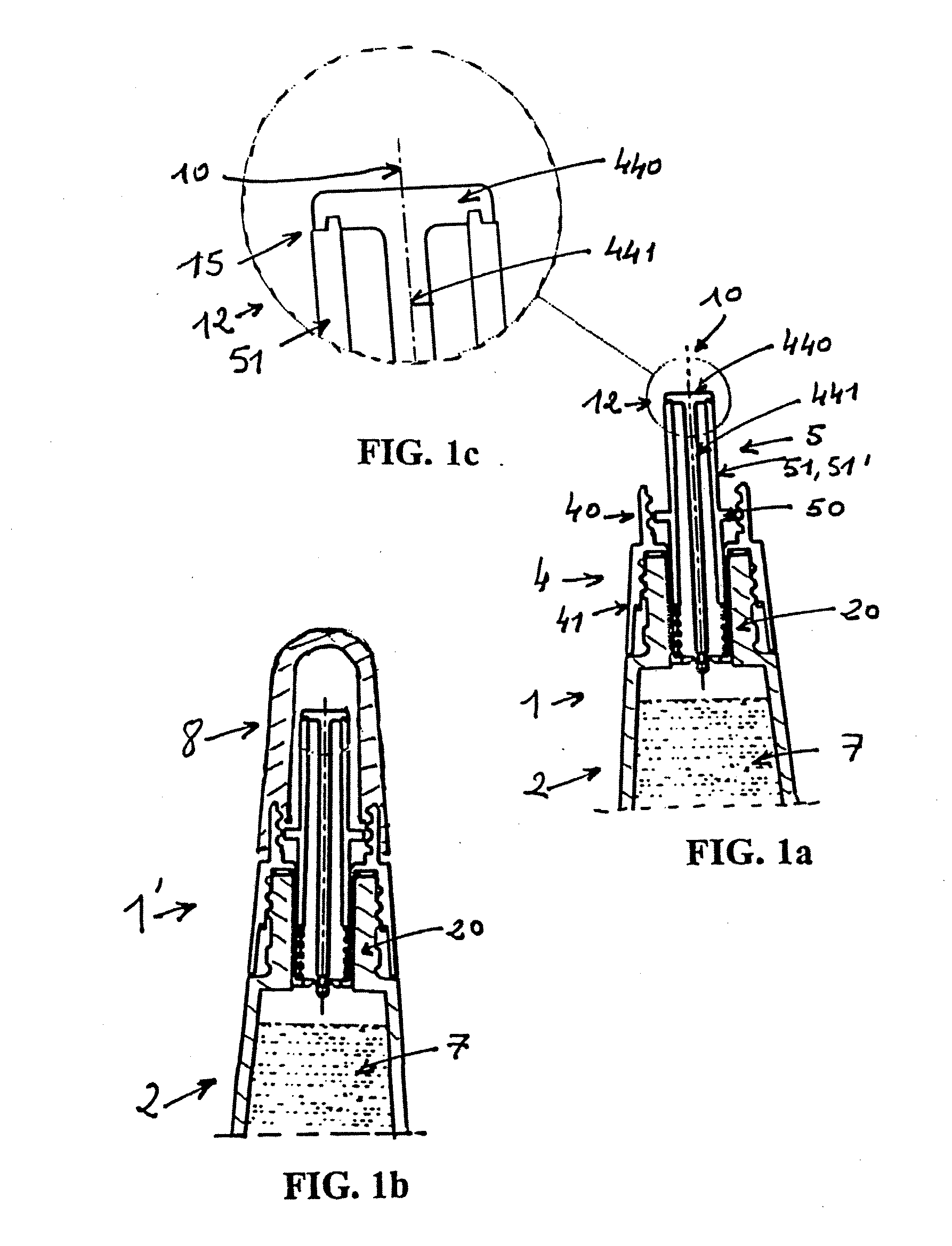
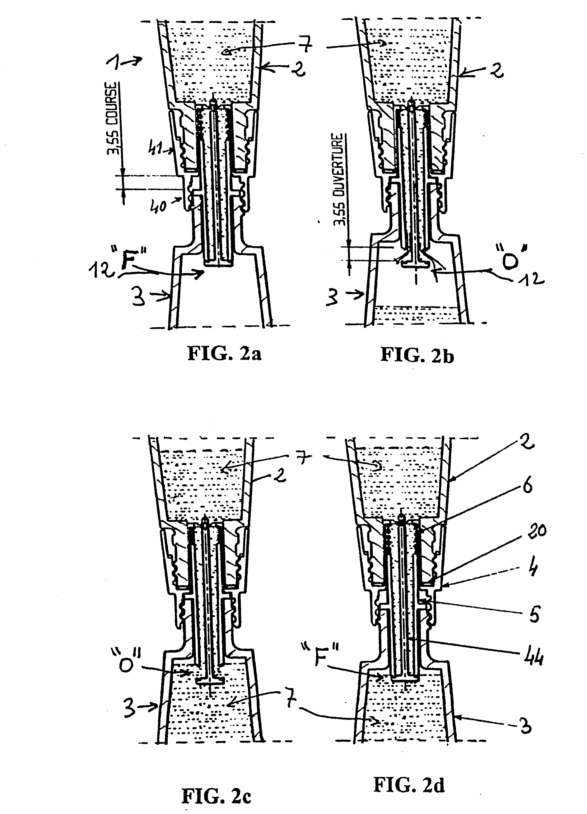
[0076]Device A was manufactured as illustrated in FIGS. 1a to 4a. To do this, thermoplastic material molding was used to manufacture:[0077]a) a connection component (4), which was an integral component, including: two internally threaded bearing plates (40) and (41), a median wall and an axial projection forming a tube portion and more specifically a lower tube portion fitted with a bottom having at least one orifice,[0078]b) a movable component, which was a unitary component, including a peripheral ring (50, 50′) and a central part forming a tube, and[0079]c) a central component (44), which was a unitary component, including the upper flap valve (440), the axial rod the lower end of which includes a means for snapping into the bottom.

[0080]A helical spring (6, 6′) was provided as well as the second container, fitted with a second threaded neck, and filled with liquid product intended to refill the first container.

[0081]These components were assembled by placing the spring in the lo...

example 2

[0083]Device B was manufactured as illustrated in FIGS. 5a and 5b. In this case, thermoplastic material molding was used to manufacture:[0084]a) a connection component as in device A,[0085]b) a movable component, which was a unitary component, including a peripheral ring (50, 50′) and a central part including a tube and an axial separation wall (52) forming the rod or axial wall and fitted with a lower snap-on end (517),[0086]c) a lower flap valve including a central snap-on orifice of diameter selected so that its lower edge (516) is able to be stopped against the lower end of the lower tube portion.

[0087]A helical spring (6, 6′) was provided as well as the second container (2). These components were assembled by snapping on the flap valve and the lower end (517) of the movable component (5).

example 3

[0088]Device C was manufactured as shown in FIGS. 6a and 6b. In this case, thermoplastic material molding was used to manufacture:[0089]a) a connection component (4), which was a unitary component, including a lower tube portion without a bottom (430),[0090]b) a movable component, which was a unitary component, including a peripheral ring (50, 50′) and a central part including a tube and an axial separation wall (52) forming the rod or axial wall integral with a lower flap valve (512). The lower flap valve includes a flexible outer edge (516′) able, by its shape, to be stopped against the lower end of the lower tube portion.

[0091]A helical spring (6, 6′) was provided as well as the second container (2). These components were assembled by forcibly snapping the movable component into the connection component (4), with the lower edge (516′) ensuring both the assembly of these two components and the tightness of the lower valve (12′).


PUM

PropertyMeasurementUnit
Lengthaaaaaaaaaa
Lengthaaaaaaaaaa
Flow rateaaaaaaaaaa

Abstract

A device for refilling a first container, fitted with a threaded first neck and a vaporization head, includes a second container for a liquid, a connection component including a first bearing plate for engaging the first neck and a second bearing plate engaging the second container, a median wall including a central orifice, and a means of closing the second container or the central orifice. The connection component engages an axially movable component capable of sliding inside the connection component, to form a valve, the movable component being able to move, under the action of an axial constraint, from a closed position “F” to an open position “O”, or, under the action of a spring, from the position “O” to the position “F”. The movable component includes a radial projection for engaging the first neck so that the first neck exerts an axial constraint on the radial projection.

Description

FIELD OF THE INVENTION[0001]The invention relates to the field of cosmetic product dispensers. More particularly, embodiments of the invention relate to the field of perfume dispensers, including refillable dispensers.BACKGROUND OF THE INVENTION[0002]Perfume bottle refills typically include containers or bottles that comprise a threaded neck, closed with a threaded plug. Similarly, refillable dispensers typically include a spray head screwed into a bottle that comprises a threaded neck. To refill the dispenser, the usual way of proceeding is to unscrew the vaporization head and to decant the refill content manually, after unscrewing its plug.[0003]Using a refill is desirable when the quality and price of the dispenser with head render it essentially a non-disposable object. Conversely, the value of a refill for the refillable dispenser is related more to the value of its content than to that of the container forming the refill, with the result that, since it is of little intrinsic v...

Claims


Application Information

Patent Timeline
IPC IPC(8): B65B3/04B67D7/06
CPCB05B11/0097B65D47/20B65D71/502B65D47/248A45D34/02A45D2034/002A45D34/00
Inventor DIEUDONAT, FABRICEMILESI, FREDERIC
Owner ALCAN PACKAGING BEAUTY SERVICES
Why Eureka
Try Eureka