Track and guide system for a door

a technology of track and guide system and door, which is applied in the field of doors, can solve the problems of significant wear on the gear that moves the drive strip, and the complex collection of numerous parts of the patent door

Active Publication Date: 2007-12-06
RITE HITE HLDG CORP
View PDF98 Cites 35 Cited by
  • Summary
  • Abstract
  • Description
  • Claims
  • Application Information

AI Technical Summary

Benefits of technology

[0011]In some embodiments, the door panel breaks away from its track without creating loose pieces in the track or on the panel.
[0014]In some embodiments, a drive strip for the door panel includes spherical projections that smoothen a breakaway function and smoothen the engagement with a drive gear.
[0016]In some embodiments, the drive strip's flexibility allows it to flex one way as it travels past a drive gear and bend an opposite way as the door panel moves onto a storage track.
[0021]In some embodiments, the flexible door panel can be opened to a loosely coiled configuration to permit ventilation through the coiled panel and / or to help prevent a plastic window on the panel from scratched by other sections of the panel.
[0022]In some embodiments, a stiffener is attached to an upper edge of the door's panel to help prevent the upper edge from whipping centrifugally outward as the panel is wrapped into a coiled configuration.
[0023]In some embodiments, the door includes a horizontal drum that creates a bend in the door's panel to help prevent the panel from sagging.

Problems solved by technology

Although the force-feed system and breakaway feature provide significant benefits, the patented door includes a complicated collection of numerous parts.
Such a material, particularly if it has sharp edges, might cause significant wear on the gear that moves the drive strip.

Method used


Image

  • Track and guide system for a door
  • Track and guide system for a door
  • Track and guide system for a door

Examples


Embodiment Construction

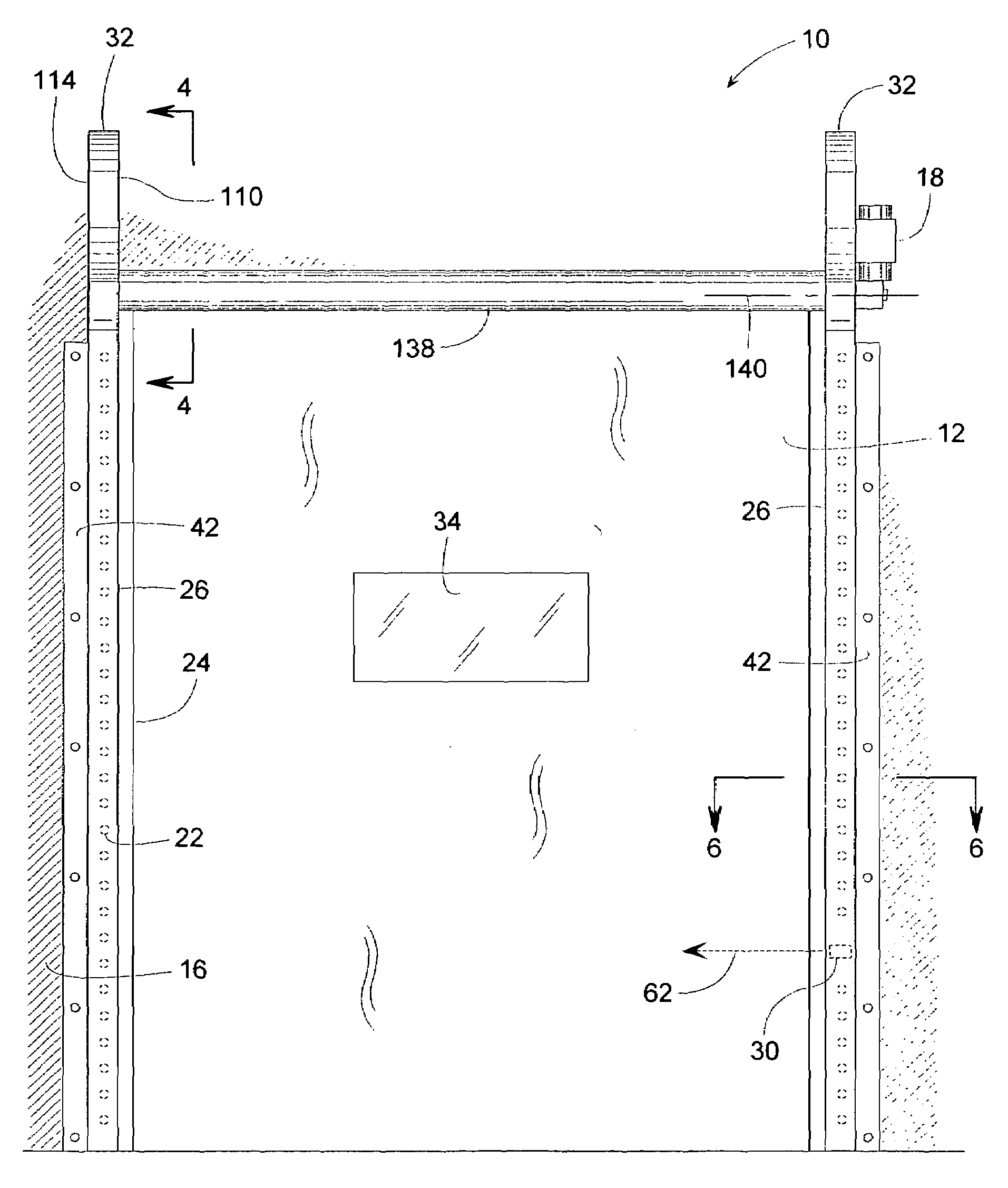
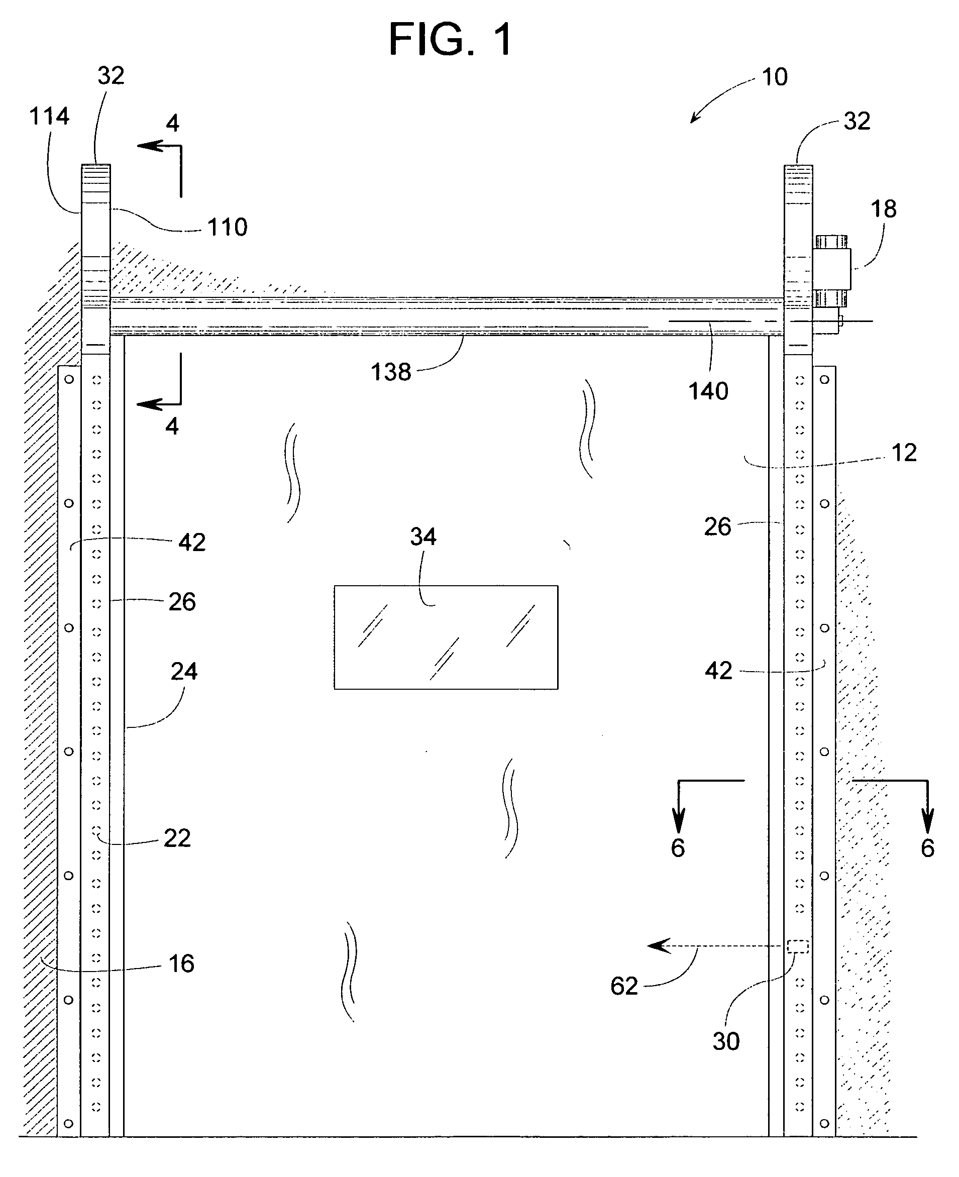
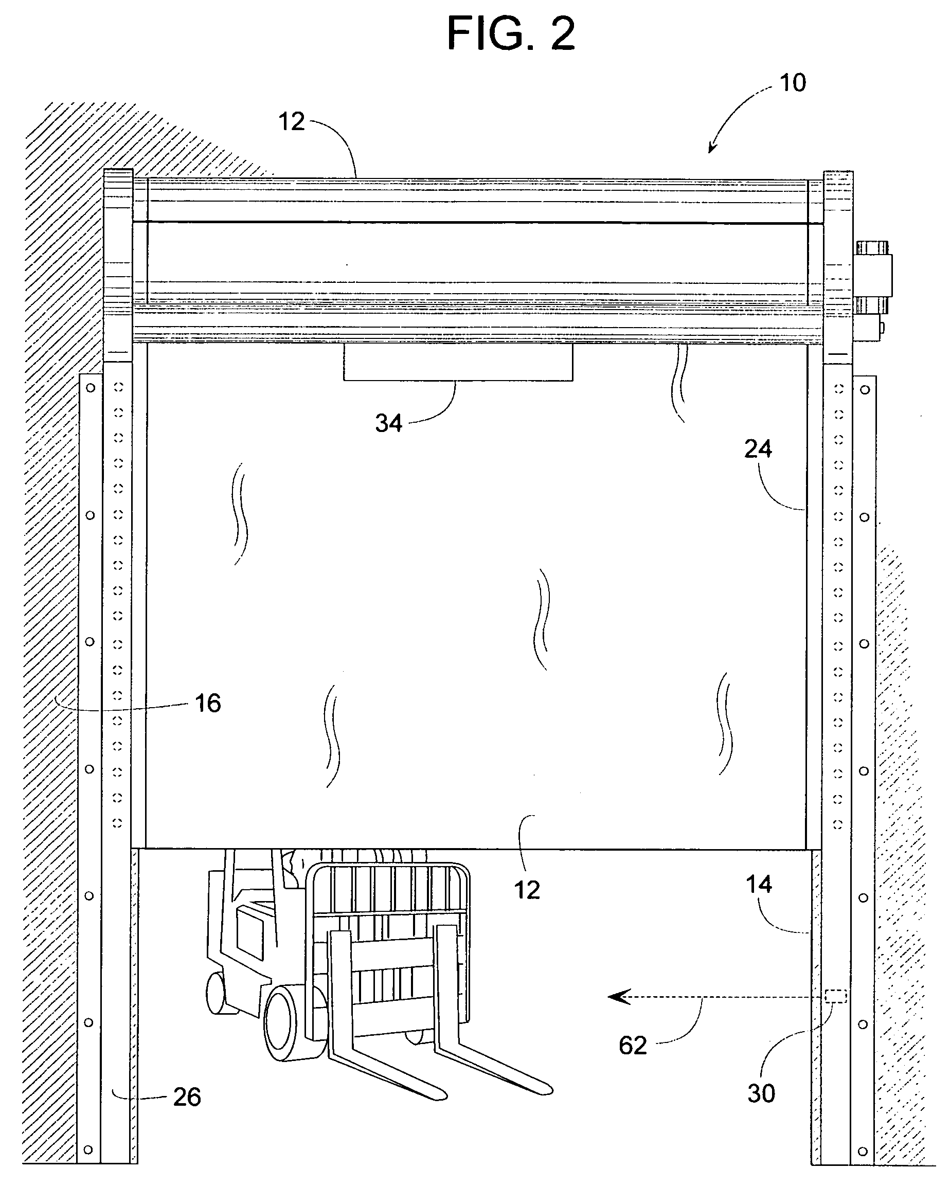
[0045]A door system 10, shown in FIGS. 1-5, includes a panel 12 that moves generally vertically between a closed position (FIGS. 1 and 4) and an open position (FIGS. 3 and 5). FIG. 2 shows panel 12 at an intermediate position relative to a doorway 14 in a wall 16.

[0046]The panel shown in FIGS. 1-5 illustratively includes a flexible sheet of a heavy duty industrial fabric as is common in the art. The drive strip and guide / retention system forming part of the inventive aspect of this the description are not limited to combination with a flexible sheet such as a fabric curtain to form the panel. Rather, the system disclosed herein could be used to drive and guide a variety of other panel structures of which it would form a part—such as a so-called rolling steel door with generally rigid, horizontally-extending slats that are hingedly interconnected. The drive system could also be a part of a unitary rigid panel. Use as a part of a flexible fabric panel having additional structure is al...


PUM


Abstract

A vertically operating door and its drive system can be configured to push a door panel along a track to various overhead storage configurations including vertical, horizontal. inclined and coiled. Semi-flexible drive strips extend continuously along lateral edges of the curtain. The system includes a drive gear that engages a series of projections on at least one drive strip so that the gear can push the door between its open and closed positions. To protect the door from being damaged by collisions, the track can include a breakaway feature that allows at least a portion of the panel with its drive strip to separate from the track without permanent distortion. The drive strip and panel remain together as they break away from the track. The threshold of the breakaway force can be changed by selecting a retention strip from a plurality of interchangeable strips having different degrees of flexibility.

Description

FIELD OF THE DISCLOSURE[0001]The present disclosure generally pertains to doors with a retractable panel and more specifically to a drive and / or a guide system for such a door.BACKGROUND OF RELATED ART[0002]Many vertically operating doors have a pliable panel or curtain that opens by moving from a vertical set of tracks installed along the lateral edges of a doorway to an overhead storage system. The storage system can vary depending on the available space above the doorway and other considerations. An overhead storage system, for instance, can be in the form of a take-up roller that draws in the curtain to open the door; or the storage system can be a set of horizontal, vertical, or inclined tracks that lead into the set of vertical tracks that line the doorway.[0003]While the take-up roller can be power-driven to raise and lower the curtain, doors having other types of overhead storage may require some other means for operating the door. Thus, door manufactures often need to offer...

Claims


Application Information

Patent Timeline
Patent Type & Authority Applications(United States)
IPC IPC(8): E06B9/17E06B9/56
CPCE06B9/13E06B9/581E06B9/56E06B9/17
Inventor DONDLINGER, JASONHARDISON, CARLJANSEN, TOMSCHULTE, PETER S.
Owner RITE HITE HLDG CORP
Why Eureka
Try Eureka