Comestible fluid rack and rail apparatus and method

a technology of fluid racks and rails, applied in the direction of cabinets, dismountable cabinets, show hangers, etc., can solve the problems of inability to change the capacity of such racks, inadequate provisions, and often inadequate needs of many users, so as to effectively match the needs of users, expand or reduce the amount of available space, and quickly disassemble and transport

Inactive Publication Date: 2007-12-06
PENTAIR FLOW TECH INC
View PDF0 Cites 30 Cited by
  • Summary
  • Abstract
  • Description
  • Claims
  • Application Information

AI Technical Summary

Benefits of technology

[0009] In some embodiments, the comestible fluid container rack includes stackable rack modules. The rack modules allow a user to expand or reduce the amount of available space for comestible fluid containers in the rack by stacking additional rack modules upon one another or by removing one or more rack modules from a stack, respectively. This can enable users to purchase limited numbers of rack modules at a time to more effectively match the needs of the user. In some cases, one or more of the rack modules can be connected to vertically adjacent rack modules (e.g., located above or below the rack module(s)) by one or more couplings. The couplings can enable rack modules to be vertically stacked in a stable manner, and can permit the rack modules to be quickly disassembled, transported, and reassembled as needed. In some embodiments, the rack modules can be disassembled, transported, and / or re-assembled without disturbing comestible fluid containers and comestible fluid dispensing components (such as comestible fluid conduits, valves, pumps, regulators, filters, and the like) on the rack modules.
[0010] The comestible fluid container rack of the present invention can have rack modules with telescoping rails enabling a user to adjust the space between vertical supports of the rack. This feature can permit a user to adjust the rack or rack modules to fit comestible fluid containers of different sizes. In some embodiments, each rack module can be independently adjusted to accommodate comestible fluid containers of different sizes. This feature can reduce the need for users to rearrange or relocate comestible fluid containers when containers of different sizes are to be placed on the rack.
[0011] Another aspect of the present invention relates to the manner in which comestible fluid dispensing components are mounted (whether on a comestible fluid container rack as described above or to another structure). In particular, some embodiments of the present invention provide a bracket to which a valve, pump, regulator, filter, or other fluid dispensing system component can be releasably mounted. The bracket can be moved and secured to different positions along a rail in order to provide mounting flexibility for installers, those who maintain or service the comestible fluid dispensing system (or components thereof), and other users. For example, the bracket can be slidable and securable to different positions along the rail. If desired, the rail can be attached to a comestible fluid container rack, such as to the vertical supports of a rack.
[0012] In some embodiments of the present invention, a comestible fluid container rack is provided having one or more supports on the rack positioned to support one or more comestible fluid containers. Each support can include a brace adapted to hold and / or support one or more comestible fluid conduits associated with the comestible fluid containers. In this manner, the braces can be employed to organize and secure the comestible fluid conduits in the rack, avoiding the conventional practice of haphazardly routing unsecured comestible fluid conduits in the rack.

Problems solved by technology

Currently available comestible fluid container racks are often inadequate for the needs of many users, and even for the process of dispensing comestible fluid from containers on such racks (e.g. in post-mix preparation and in the preparation of other types of beverages).
Problems and limitations with conventional comestible fluid container racks include the inability to change the capacity of such racks (whether by changing the size of a rack or by easily and readily adding to the rack), inadequate provisions for mounting or organizing components associated with the dispense of comestible fluid from the containers, and rack designs that are difficult and time-consuming to set up, disassemble, and / or transport.
The mounting and arrangement of such components in comestible fluid storage and dispensing systems also presents problems and limitations well known in the art (regardless of whether a rack as described above is employed).
By way of example only, these problems and limitations include haphazard and disorganized systems and systems in which systems components are difficult and time-consuming to service, replace, and maintain.
In some cases, it can be difficult for a user or other party to even identify which components in the system are associated with which other components.

Method used


Image

  • Comestible fluid rack and rail apparatus and method
  • Comestible fluid rack and rail apparatus and method
  • Comestible fluid rack and rail apparatus and method

Examples


Embodiment Construction

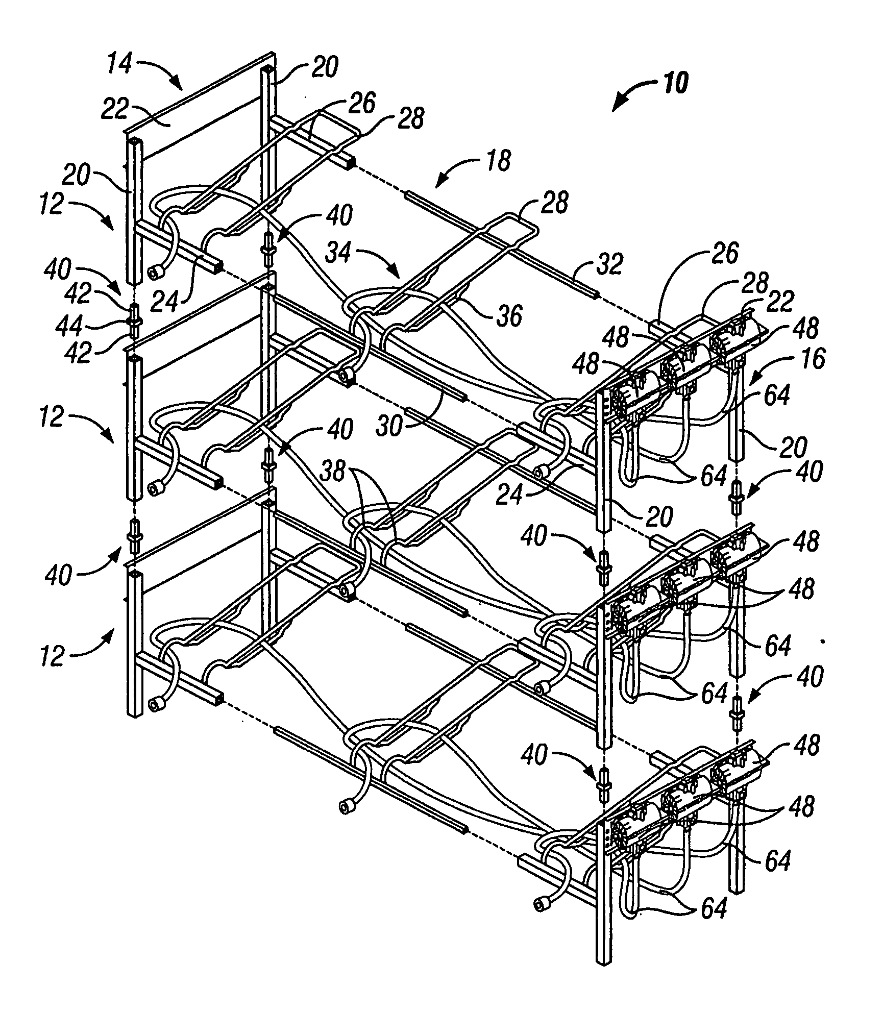
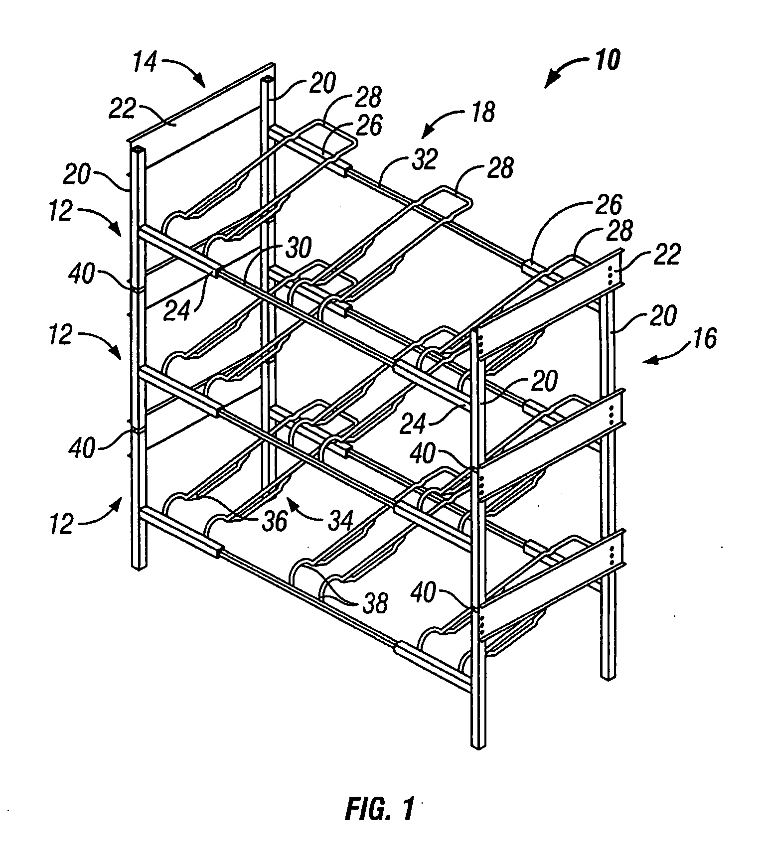
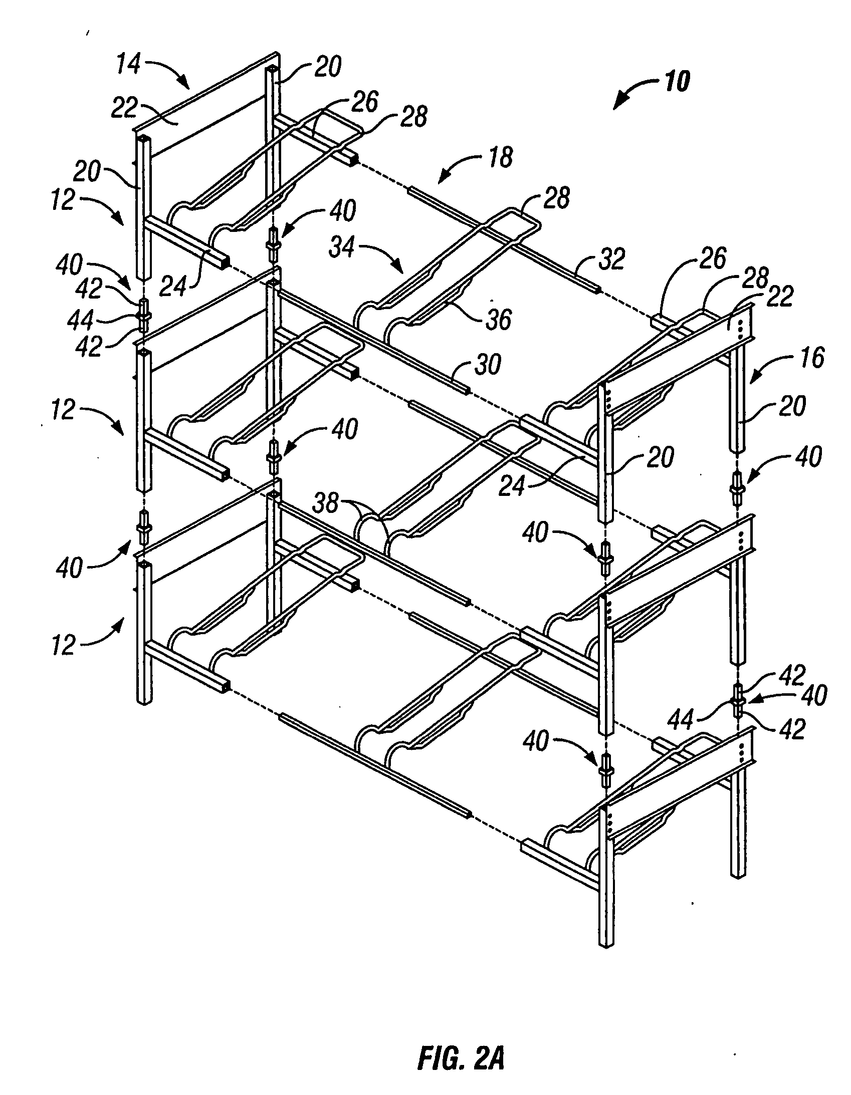
[0028] An embodiment of a comestible fluid container rack according to the present invention is illustrated in FIGS. 1 and 2A. The illustrated rack (indicated generally at 10) is adapted for holding bag-in-box type comestible fluid containers. Bag-in-box comestible fluid containers typically have a port to which a conduit 64 can be releasably connected and through which comestible fluid can be pumped, drained, or otherwise removed from the container. Although the port in such containers is typically located near the bottom of the container, the port can be in any location on the container depending at least in part upon the manner in which comestible fluid is removed from the container. Bag-in-box comestible fluid containers are well-known to those in the art and are not therefore described further herein.

[0029] Although the illustrated embodiment of the rack 10 is adapted for holding bag-in-box type comestible fluid containers, it will be appreciated that the rack 10 can be adapte...


PUM


Abstract

Some embodiments of the present invention provide a support adapted to support a comestible fluid container on a comestible fluid container rack, and a container rack having such a support. The support can include a first portion extending from a stretcher of the comestible fluid container rack and a second portion extending substantially laterally from the first portion to support the comestible fluid container thereon.

Description

RELATED APPLICATIONS [0001] This is a continuation patent application of U.S. patent application Ser. No. 10 / 773,110 filed on Feb. 4, 2004, which is a continuation-in-part application of U.S. patent application Ser. No. 10 / 211,883 filed on Aug. 1, 2002 and issued as U.S. Pat. No. 6,834,768, both of which are incorporated herein by reference.BACKGROUND OF THE INVENTION [0002] Racks of many different configurations are currently available in the food and beverage industry. A number of such racks are employed to store any type of beverage container, including without limitation bottles, boxes, crates, bags, kegs, barrels, and other containers capable of holding fluid. By way of example only, racks are often employed to support syrup containers used in post-mix beverage blending. As is well known in the art, the syrup in such containers is pumped, drained, or otherwise removed from the containers and is often mixed with water or water and gas to yield a post-mix beverage. In those cases...

Claims


Application Information

Patent Timeline
Patent Type & Authority Applications(United States)
IPC IPC(8): A47B43/00A47B45/00A47B73/00A47F5/13
CPCA47B45/00A47B73/00A47F5/13A47B81/007A47B73/002
Inventor JERSEY, STEVEN T.CHUNG, WILLIAM W.BROYLES, LARRY D.HENRY, MICHAEL D.SMITH, MICHAEL R.
Owner PENTAIR FLOW TECH INC
Why Eureka
Try Eureka