
Wheel rim

Inactive Publication Date: 2007-12-06
ALEX GLOBAL TECH
View PDF8 Cites 7 Cited by
  • Summary
  • Abstract
  • Description
  • Claims
  • Application Information

AI Technical Summary

Benefits of technology

[0009]The object of the present invention is to provide a wheel rim, which can be assembled relatively simply and easily.

Problems solved by technology

However, assembling the guide tubes 27 in the wheel rim through the first through holes 220 of the reinforcing wall 22 is time-consuming.
Furthermore, the presence of the guide tubes 27 increases the overall weight of the wheel rim.

Method used


Image

  • Wheel rim
  • Wheel rim
  • Wheel rim

Examples


Embodiment Construction

[0026]Before the present invention is described in greater detail, it should be noted that like elements are denoted by the same reference numerals throughout the disclosure.

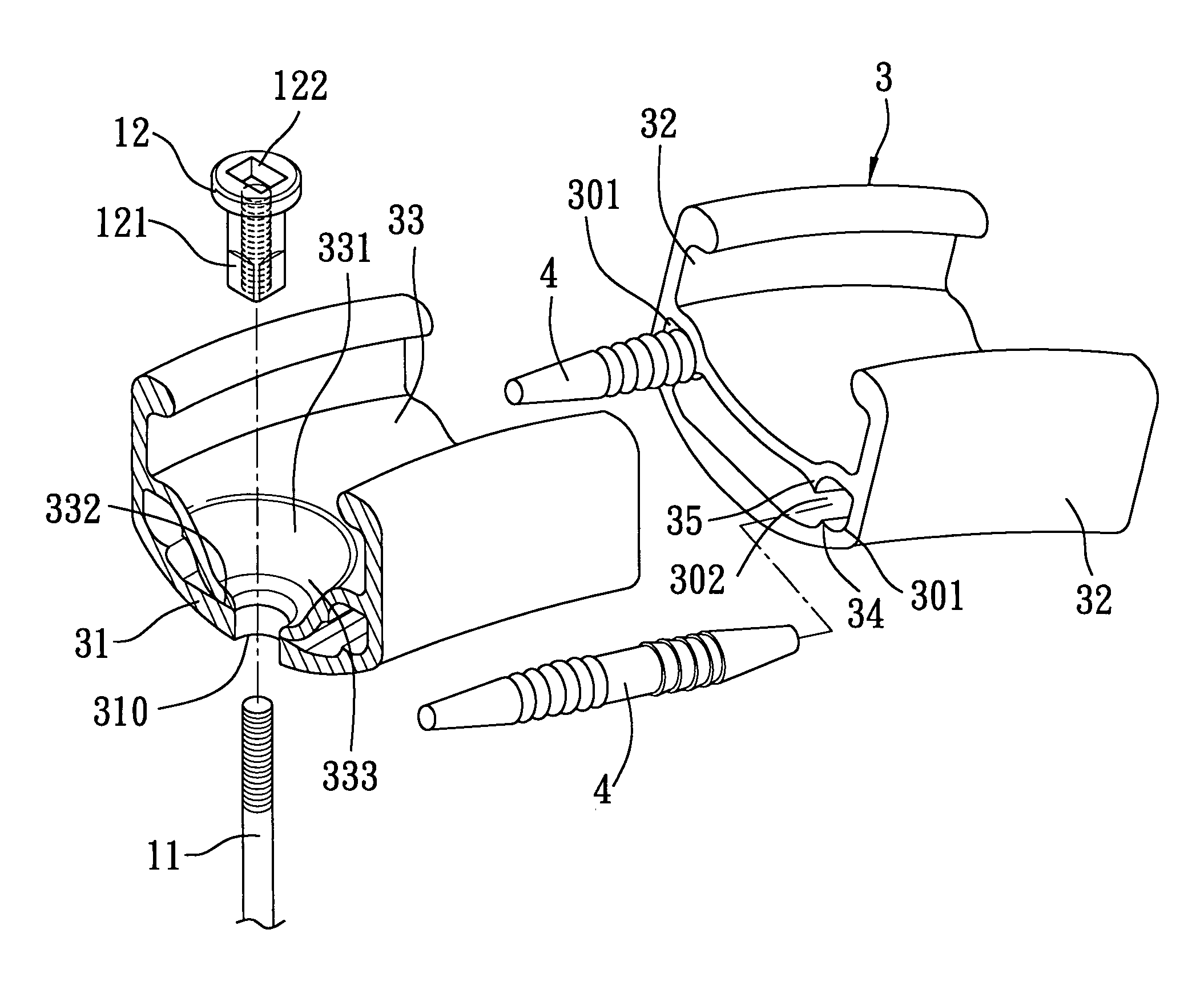
[0027]Referring to FIGS. 7, 8, 9, and 10, the first preferred embodiment of a wheel rim according to this invention is used for assembly with a tire 10 and a plurality of spokes 11, and includes a wheel rim body 3 and two engaging pins 4.

[0028]The wheel rim body 3 includes an annular base wall 31, annular left and right tire-retaining walls 32, an annular reinforcing wall 33, and a plurality of spoke-retaining studs 12.

[0029]The annular base wall 31 includes an annular array of first through holes 310 spaced apart from each other, and two first annular rib portions 34 extending along the length of the annular base wall 31 on two sides of the annular array of the first through holes 310, and protruding from the annular base wall 31 toward the annular reinforcing wall 33.

[0030]The annular left and right tire-retai...


PUM


Abstract

A wheel rim includes an annular base wall, annular left and right tire-retaining walls, and an annular reinforcing wall. The annular base wall includes an annular array of first through holes spaced apart from each other. The annular left and right tire-retaining walls are spaced apart from each other, and extend radially and outwardly from the annular base wall. The annular reinforcing wall includes an annular wall portion extending between the left and right tire-retaining walls and spaced apart from the annular base wall, and a plurality of hollow projections aligned radially and respectively with the first through holes. Each of the hollow projections defines a second through hole. Each of the hollow projections is formed as one piece with and projects from the annular wall portion of the annular reinforcing wall.

Description

BACKGROUND OF THE INVENTION[0001]1. Field of the Invention[0002]The invention relates to a wheel rim, more particularly to a wheel rim having a reinforced structure.[0003]2. Description of the Related Art[0004]Referring to FIGS. 1 and 2, a conventional wheel rim for a bicycle includes an annular base wall 21, annular left and right tire-retaining walls 23 spaced apart from each other and extending radially from the annular base wall 21, and an annular reinforcing wall 22 extending between the left and right tire-retaining walls 23 and spaced apart from the annular base wall 21. A tire 28 can be retained by the annular left and right tire-retaining walls 23. In order to position a plurality of spoke-retaining studs 26, each of which has a head 262 and a hollow shaft 261 extending from the head 262, in the wheel rim, the annular reinforcing wall 22 is provided with an annular array of first through holes 220, and the annular base wall 21 is provided with a plurality of second through ...

Claims


Application Information

Patent Timeline
IPC IPC(8): B60B21/06
CPCB60B1/041B60B1/044B60B21/025B60B25/02B60B21/04B60B21/062B60B21/026
Inventor CHEN, CHAO-YING
Owner ALEX GLOBAL TECH
Features
  • Generate Ideas
  • Intellectual Property
  • Life Sciences
  • Materials
  • Tech Scout
  • Unparalleled Data Quality
  • Higher Quality Content
  • 60% Fewer Hallucinations
Learn More