RFID carrier sensing method and FRID system using this FRID carrier sensing method

Inactive Publication Date: 2007-12-06
FUJITSU LTD
View PDF4 Cites 10 Cited by
  • Summary
  • Abstract
  • Description
  • Claims
  • Application Information

AI Technical Summary

Benefits of technology

[0028] The present invention makes it possible to create a high probability that a spare cha

Problems solved by technology

In FIG. 1, a signal transmitted by the respective reader/writer #1 (#2) has an interference 3 with respect to the other reader/writer #2 (#1), and there is the problem that the reception performance of the reader/writers #1 and #2 deteriorates.
A former method that proceeds according to the flow of FIG. 2, i.e. which involves performing carrier sensing as described hereinabove to search for a frequency channel that is not be

Method used


Image

  • RFID carrier sensing method and FRID system using this FRID carrier sensing method
  • RFID carrier sensing method and FRID system using this FRID carrier sensing method
  • RFID carrier sensing method and FRID system using this FRID carrier sensing method

Examples


Example

[0040] An embodiment of the present invention will be described hereinbelow in accordance with the drawings.

[0041] The embodiments described hereinbelow permit an understanding of the present invention and the technical scope of the present invention is not limited thereto.

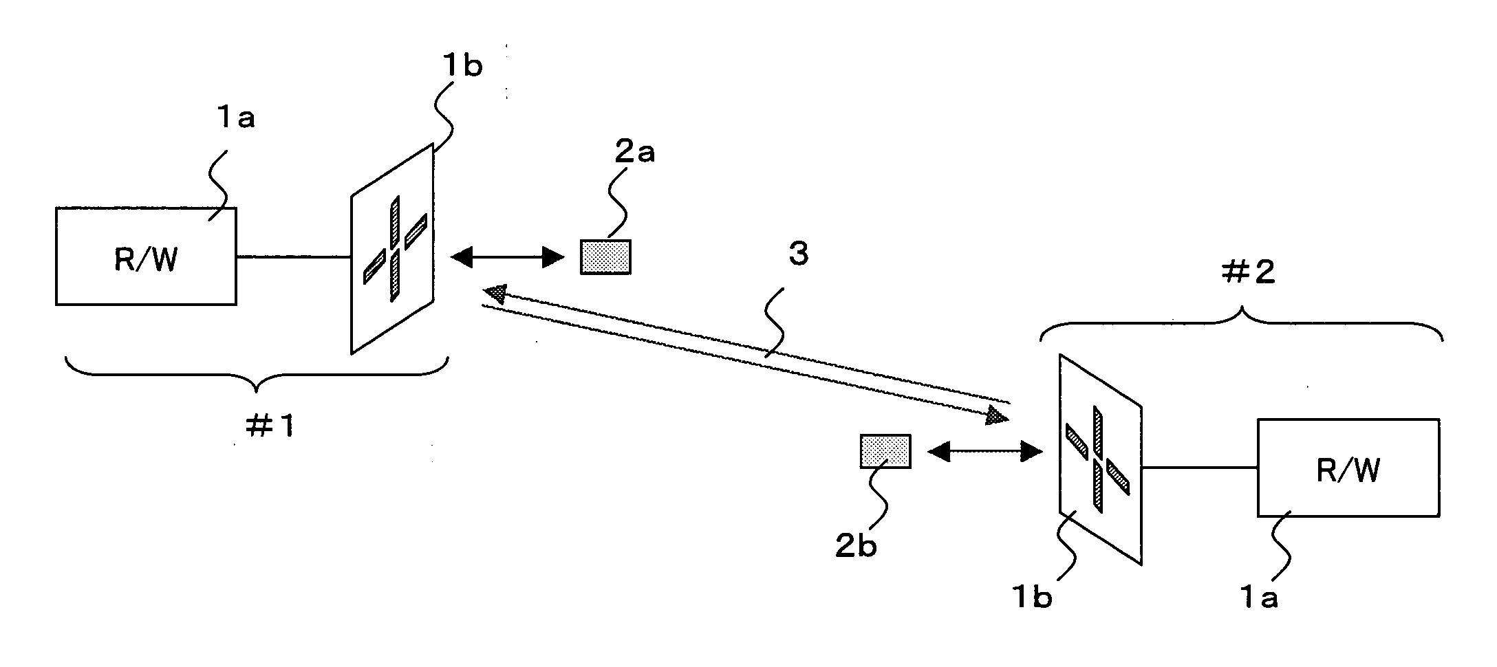
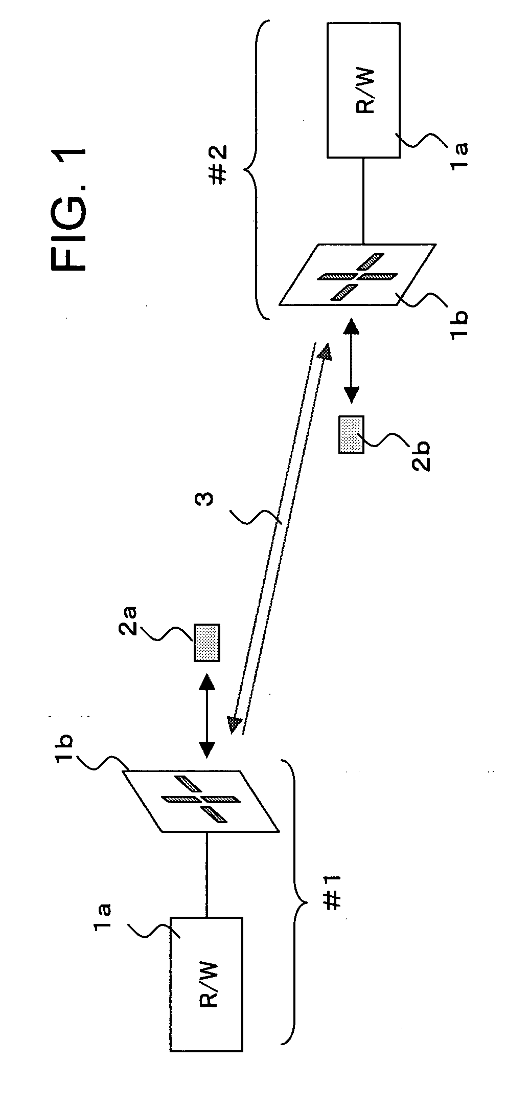
[0042]FIG. 4 shows a case where a plurality of reader / writers #1 and #2 are operated adjacent to one another as a RFID system and, in contrast to FIG. 1, when carrier sensing is the characteristic of the present invention, a function 4 that controls the polarization direction of the antenna 1b of the reader / writer is provided.

[0043]FIG. 5 is a conceptual view of a constitutional example of the reader / writer #1 and #2 to which the present invention is applied.

[0044] In FIG. 5, antenna 1b comprises an antenna element 10, and a polarization direction control section 20. The polarization direction control section 20 shown in FIG. 5 has a function to switch the polarization direction of the antenna element 10 to ri...


PUM


Abstract

An RFID system that is capable of increasing the probability of a spare channel being detected and reducing the influence of interference between reader/writers comprises: a reader/writer which has a reader/writer main body section and an antenna capable of polarization switching, and which sends a continuous carrier wave; and a tag which uses tag information to modulate the continuous carrier wave and sends back a response signal to the reader/writer. The reader/writer main body section judges the level of a received interference signal and determines a channel and polarization direction for which the level of the interference signal is equal to or less than a threshold value, and receives a response signal from the tag on the determined channel and in the polarization direction.

Description

CROSS-REFERENCE TO RELATED APPLICATIONS [0001] This application is a continuation of international application PCT / JP2005 / 001319, filed on Jan. 31, 2005.TECHNICAL FIELD [0002] The present invention relates to a radio frequency ID (RFID: Radio Frequency Identification) carrier sensing method and an RFID reader / writer and RFID system that employ the radio frequency ID. BACKGROUND ART [0003] In recent years, in the reading of ID information that is recorded on tags, systems that perform reading by utilizing magnetic coupling with tags or RFID systems that use wireless frequencies to read tag information have been developed and operated. [0004] For the latter RFID system that performs reading by using wireless frequencies, European standards have been disclosed by the ETSI (European Telecommunications Standards Institute) (Draft ETSI EN 302 208-1V1.1.1 (2003-12)) as an example. The usage of an RFID system that employs the 865 MHz to 868 MHz band at a maximum power of 2 W was disclosed i...

Claims


Application Information

Patent Timeline
IPC IPC(8): H04Q5/22
CPCG06K7/0008H04B7/10G06K7/10356
Inventor TANAKA, YOSHINORI
Owner FUJITSU LTD
Why Eureka
Try Eureka