Method and system for reduction of time variance of packets received from bonded communication links

Active Publication Date: 2014-08-07
PISMO LABS TECH
View PDF3 Cites 9 Cited by
  • Summary
  • Abstract
  • Description
  • Claims
  • Application Information

AI Technical Summary

Benefits of technology

[0005]Network traffic received from bonded communication links are delivered to a device, a network interface or a process of a destination network device in sequence with higher probability and less time variance comparing to a destination network device without implementing this invention.
[0006]The invention includes an implementation that reduces the time variance of delivering packets to a device, a network interlace or a process of a destination network device (DND) according to latency difference among bonded communication links (Latency Difference). The sequence number (SEQ) of the packets received may also be used with latency difference to reduce the time variance. It is a common knowledge that a source network device (SND), which has the capabilities of distributing packets across bonded communication links, assigns consecutive SEQ to packets before sending the packets to the bonded communication links.
[0007]The value of Latency Difference is based on the time difference of packets with consecutive SEQ arriving at the DND through the bonded communication links. The value of Latency Difference may change as network conditions of bonded communication links change.
[0008]In one implementation, the DND delivers a packet without storing the packet to a queue if the packet is arriving from the one of the bonded communication links which has the largest latency.
[0009]In one implementation, at the DND, an expected SEQ (E-SEQ) is calculated based on Latency Difference

Problems solved by technology

Each packet, when arriving at a DND, may experience different delay as each of the bonded communication links may have different latency and different amount of bandwidth available.
Also, some of the packets may never arrive at the DND bec

Method used


Image

  • Method and system for reduction of time variance of packets received from bonded communication links
  • Method and system for reduction of time variance of packets received from bonded communication links
  • Method and system for reduction of time variance of packets received from bonded communication links

Examples


Embodiment Construction

[0023]Detailed Descriptions

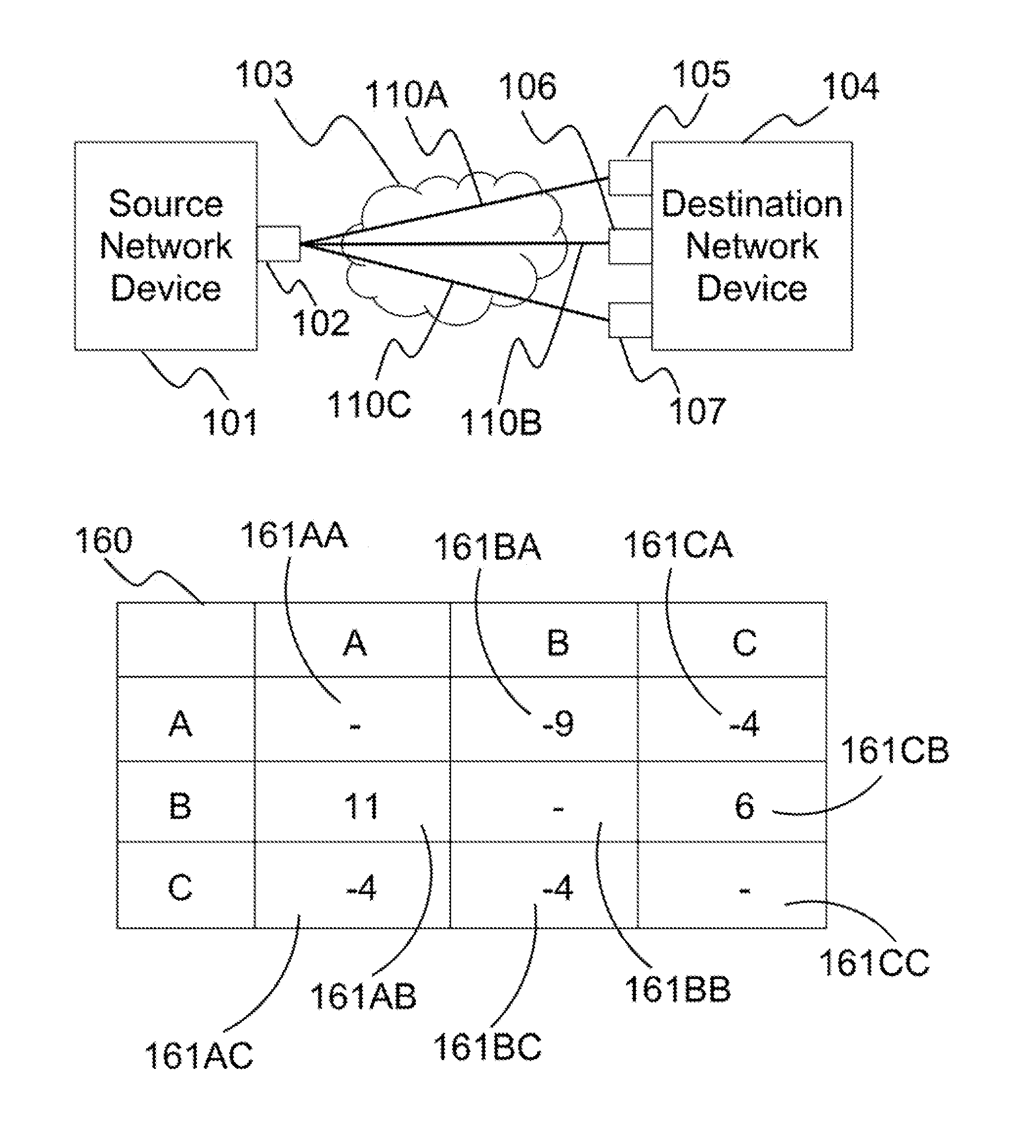
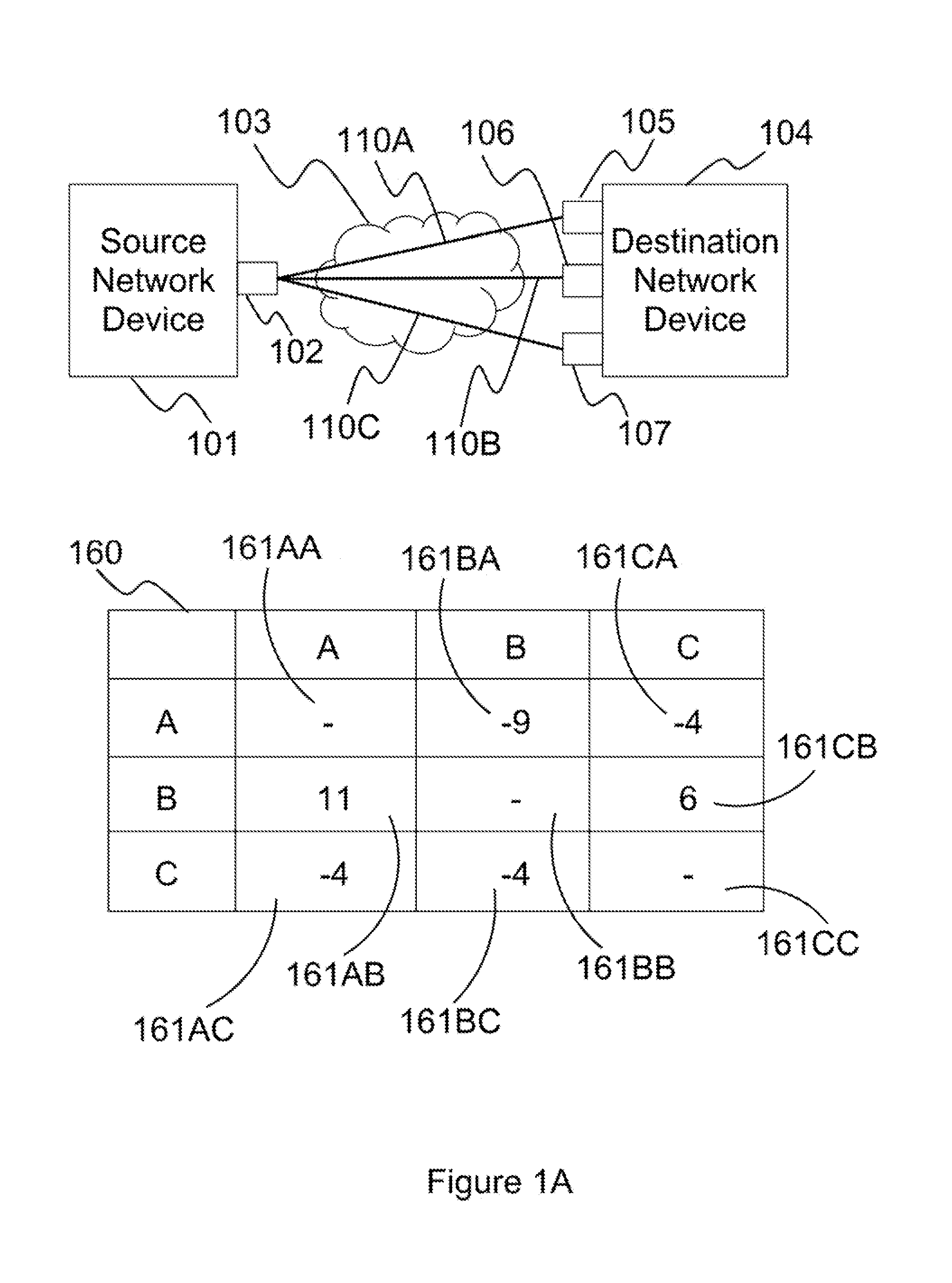
[0024]Latency difference among bonded communication links is calculated by measuring the time difference of two packets, which are sent consecutively from a source network device, arriving at a destination network device through two of the bonded communication links. As these two packets arrive at the destination network device through two different links, each packet may arrive at the destination network device at different time due to different network conditions of these two different links and the time the packets leaving the source network device.

[0025]On the other hand, if consecutive packets are sent from the source network device to the destination network device through one of the bonded communication links, it is assumed that there is no latency difference between these consecutive packets because these two packets should experience similar network conditions.

[0026]As packets are continuously sent from the source network device to the destination...


PUM


Abstract

Method and system for reduction of time variance of packets received from bonded communication links. Embodiments of present inventions can be applied to bonded communication links, including wireless connection, Ethernet connection, Internet Protocol connection, asynchronous transfer mode, virtual private network, WiFi, high-speed downlink packet access, GPRS, LTE, X.25 and etc. The present invention presents methods comprising the steps of determining latency difference among bonded communication links, receiving one or more packets from the bonded communication links, and delivering the one or more packets according to the latency difference. The present invention also present systems comprising one or more network interfaces for receiving one or more packets from the bonded communication links communication network and one or more control modules configured for determining latency difference among a bonded communication links communication network, and for delivering the one or more packets according to the latency difference.

Description

TECHNICAL FIELD[0001]This invention relates in general to network communications and, more particularly, to a method and system for processing packets received from bonded communication links according to latency difference among the bonded communication links and sequence numbers.BACKGROUND ART[0002]Network devices, such as routers, may be configured to distribute outgoing traffic, which may be originated from an application within a local area network or from a network device, across bonded communication links associated with multiple egress interfaces, logic connections, network tunnels, virtual private networks and etc. There are a few bonded communication links implementations, such as bonding, and PPP Multilink Protocol. Network traffic can be usually carried by packets through wired or wireless and public or private networks through bonded communication links. In order to allow a destination network device (DND) to determine the sequence of the packets, it is a common practic...

Claims


Application Information

Patent Timeline
IPC IPC(8): H04L12/863H04L29/08H04L47/41H04L47/32H04L47/56
CPCH04L69/324H04L47/626H04L12/2867H04L47/283H04L47/32H04L47/34H04L43/087H04L43/0894H04L47/28H04L47/323H04L47/41H04L47/621Y02D30/50H04L43/0852H04L47/562H04L49/9084
Inventor CHAU, KIT WAICHAN, ALEX WING HONGSUNG, PATRICK HO WAICHAN, HO MING
Owner PISMO LABS TECH
Why Eureka
Try Eureka